Numerical toolbox for design of fluidic components and systems

a fluidic component and toolbox technology, applied in the field of fluidic components, can solve the problem that the approach is rare in fluidic applications, and achieve the effect of reducing the time required to evaluate each design

Inactive Publication Date: 2013-11-05
NAVY U S A AS REPRESENTED BY THE SEC OF THE THE
View PDF0 Cites 4 Cited by
  • Summary
  • Abstract
  • Description
  • Claims
  • Application Information

AI Technical Summary

Problems solved by technology

This approach is rare in fluidic applications due to the computational intensity of optimizing complex structures.

Method used


Image

  • Numerical toolbox for design of fluidic components and systems
  • Numerical toolbox for design of fluidic components and systems
  • Numerical toolbox for design of fluidic components and systems

Examples


Embodiment Construction

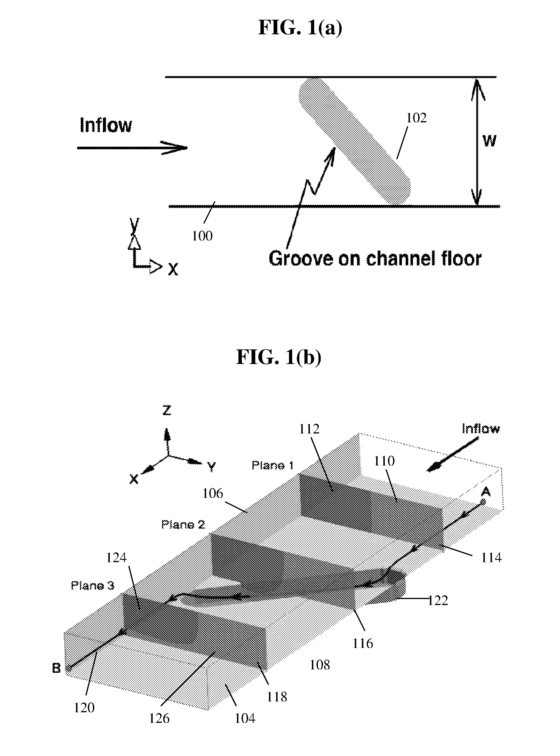
[0041]In the exemplary embodiments discussed below, the channel is linear and has a rectangular cross section. Of course any shaped channel may be used, so long as the CFD equations may be used, or experiments may be taken, to establish the a priori information on the fluid flow therein. Further, the exemplary embodiments discussed below include grooves to affect fluid flow. Of course any fluid flow-affecting feature may be used, so long as the CFD equations may be used, or experiments may be taken, to establish the a priori information on the fluid flow thereabout. Non-limiting examples of fluid flow-affecting features include bumps, fins, areas of differing surface texture, areas having fields, and areas having gradients. Still further, the exemplary embodiments discussed below include planar input and output fluid profiles. Of course any surface may be used for a fluid profile, so long as the CFD equations may be used, or experiments may be taken, or some other method used to est...


PUM


Abstract

A computational “toolbox” can be used for the a priori design of optimized fluidic components. These components include a channel under low-Reynolds number, pressure-driven flow, with an arrangement of grooves cut into the top and / or bottom to generate a tailored cross-channel flow. An advection map for each feature (i.e., groove of a particular shape and orientation) predicts the lateral transport of fluid within the channel due to that feature. Applying the advection maps in sequence generates a representation of the outflow distribution for complex designs that combine one or more features. Therefore, the effect of the complex three-dimensional flow field can be predicted without solving the governing flow equations through the composite geometry, and the resulting distribution of fluids in the channel is used to evaluate how well a component performs a specified task. The toolbox is applied to determine optimal combinations of features for specified mixer sizes and mixing metrics.

Description

BACKGROUND OF THE INVENTION[0001]The present invention is generally directed to fluidic components. A fluidic component in its broadest sense, may be considered a channel that permits flow of fluid therethrough. Non-limiting examples of fluidic components include fluidic mixers, reactors, straws, tubes, etc.[0002]Computational fluid dynamics (CFD) is playing an increasing role in the development of fluidic components, but the automatic design and optimization of new components using CFD is the exception and not the rule. Computational studies of the flow fields within components are more often used to fine-tune a near-final design or provide detailed analysis once a design is finalized. When CFD is used in design, it generally serves to replace some benchtop experiments with numerical experiments, but it leaves the “build-and-test” approach intact. Intuition and experience guide the designer through the arduous process of testing and altering a design until a satisfactory component ...

Claims


Application Information

Patent Timeline
Patent Type & Authority Patents(United States)
IPC IPC(8): G06G7/50G06F17/10G06F7/60G06G7/48
CPCG06F17/5018G06F2217/16B01J19/0093B01J2219/00889B01J2219/00995G06F30/23G06F2111/10B01F25/431B01F25/43172B01F25/431971B01F33/30B01F25/4317
Inventor HOWELL, JR., PETER B.MOTT, DAVIDGOLDEN, JOEL P.
Owner NAVY U S A AS REPRESENTED BY THE SEC OF THE THE
Why Eureka
Try Eureka