Key structure with scissors-type connecting member

a technology of connecting member and key structure, which is applied in the direction of operation facilitation, contact mechanisms, electrical appliances, etc., can solve the problem of easy fatigue of the hand of the user, and achieve the effect of enhancing the hand feel

Inactive Publication Date: 2013-11-12
PRIMAX ELECTRONICS LTD
View PDF8 Cites 56 Cited by
  • Summary
  • Abstract
  • Description
  • Claims
  • Application Information

AI Technical Summary

Benefits of technology

[0009]The present invention provides a key structure of an illuminated keyboard in order to avoid the light leakage problem and enhance the hand feel.
[0010]In accordance with an aspect of the present invention, there is provided a key structure with a scissors-type connecting member. The key structure includes a base plate, a keycap, the scissors-type connecting element and a light-emitting element. The keycap has a light-transmissible region and an extension sidewall. The light-transmissible region is located at a surface of the keycap. The extension sidewall is located at a periphery of the keycap. In addition, a protrusion structure located at a first side and a second side of the extension sidewall. The scissors-type connecting element is arranged between the base plate and the keycap for connecting the base plate and the keycap, and allowing the keycap to be moved upwardly and downwardly relative to the base plate. The light-emitting element is disposed under the keycap for emitting light beams. When the light beams are directed to the keycap, first portions of the light beams are transmitted through the light-transmissible region to illuminate the keycap, and second portions of the light beams are blocked by the protrusion structure to avoid light leakage.

Problems solved by technology

If the illuminated keyboard 1 has been used for a long term, the hand of the user is readily fatigued.

Method used


Image

  • Key structure with scissors-type connecting member
  • Key structure with scissors-type connecting member
  • Key structure with scissors-type connecting member

Examples


Embodiment Construction

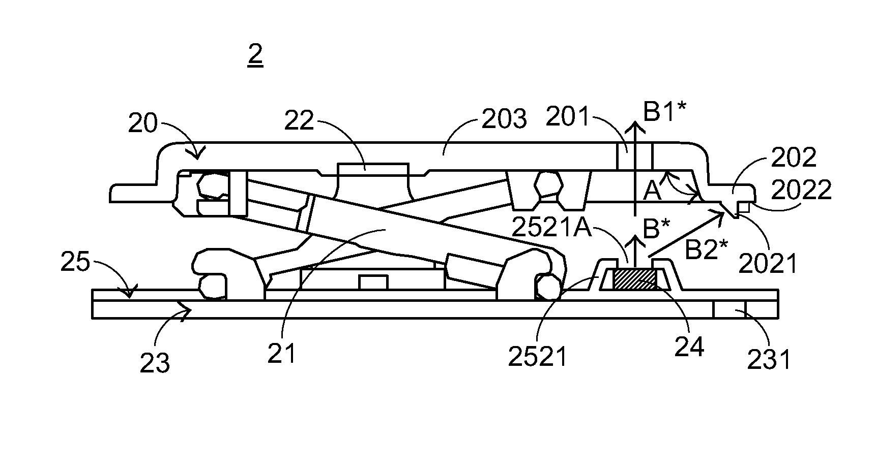
[0029]For obviating the drawbacks encountered from the prior art, the present invention provides a key structure with a scissors-type connecting member. FIG. 4 is a schematic partial side view illustrating an illuminated keyboard according to an embodiment of the present invention. The illuminated keyboard 2 comprises a plurality of key structures. Each of the key structures comprises a keycap 20, a scissors-type connecting member 21, an elastic element 22, a base plate 23, a light-emitting element 24 and a membrane module 25. The membrane module 25 comprises a membrane switch circuit member 251 and an elastic element film layer 252. From top to bottom, the keycap 20, the scissors-type connecting member 21, the elastic element 22, the elastic element film layer 252, the light-emitting element 24, the membrane switch circuit member 251 and the base plate 23 of the illuminated keyboard 2 are sequentially shown.

[0030]For clarification, a single key structure will be illustrated as foll...


PUM


Abstract

A key structure includes a keycap, a scissors-type connecting element, a membrane module, a light-emitting element and a base plate. The light-emitting element is used for emitting light beams. The keycap has a protrusion structure for blocking the light beams and preventing the light beams from leaking out through the gap between said keycap and said base plate. The base plate has a slot corresponding to the protrusion structure. When the keycap is depressed, the membrane module is pressed by the protrusion structure to be subject to deformation, so that a deformed part of the membrane module is inserted into the slot of the base plate. In such way, the hand feel of depressing the keycap is not adversely affected.

Description

FIELD OF THE INVENTION[0001]The present invention relates to a key structure, and more particularly to a key structure of an illuminated keyboard.BACKGROUND OF THE INVENTION[0002]Generally, the common input device of a computer includes a mouse, a keyboard, a trackball, and the like. For example, via the keyboard, the user may directly input characters and symbols into the computer. Consequently, the users and the manufacturers of the input devices pay more attention to keyboards. With increasing development of science and technology, the keyboard manufacturers make efforts in designing novel keyboards with diversified functions. Recently, an illuminated keyboard with an illuminating function has been disclosed in order to meet the users' requirements.[0003]Hereinafter, the outward appearance of a conventional illuminated keyboard will be illustrated with reference to FIG. 1. FIG. 1 is a schematic top view illustrating the outward appearance of a conventional illuminated keyboard. A...

Claims


Application Information

Patent Timeline
Patent Type & Authority Patents(United States)
IPC IPC(8): H01H9/00
CPCH01H13/83H01H3/125H01H9/161H01H13/702H01H2217/044H01H2219/064
Inventor JHUANG, CHUANG-SHUCHENG, HSIANG-WEN
Owner PRIMAX ELECTRONICS LTD
Why Eureka
Try Eureka