

Developer for developing electrostatic latent image, developer cartridge for developing electrostatic latent image, process cartridge, and image formation apparatus
a developer cartridge and electrostatic latent image technology, applied in the field of developing electrostatic latent image, can solve the problems of difficult adjustment of the amount of colorant, subtle changes in the color hue of images,
Inactive Publication Date: 2013-11-26
FUJIFILM BUSINESS INNOVATION CORP
View PDF11 Cites 0 Cited by
- Summary
- Abstract
- Description
- Claims
- Application Information
AI Technical Summary
Benefits of technology
The patent text discusses the use of white-colored conductive particles in a resin film layer to improve the color tone of images obtained by using a toner. The conductive particles help to maintain the color tone of the image even when the resin film layer is peeled off. The use of white-colored conductive particles is particularly useful when combined with a transparent toner. The patent also mentions the use of resin particles and conductive particles in the resin coating layer, with the conductive particles having a volume resistivity of about 102 Ω·cm or less at 20°C.
Problems solved by technology
However, because binder resins used in such a toner are also actually colored to some extent, the “transparent images” may not be completely transparent but rather have a slightly yellowish tinge, which may result in subtle changes in the color hue of the images.
However, since the colorant to be used for this purpose is used in a fairly trace amount, when the colorant is incorporated into the toner, there may be cases in which the adjustment of the amount of the colorant may be difficult, or there are irregularities from one toner to another.
Method used
View moreImage
Smart ImageViewing Examples

Examples
example 1
Preparation of Developer 1
[0178]8 parts of the transparent toner A for external addition and 100 parts of the resin coated carrier 1 are stirred with a V type blender at 40 rpm for 20 minutes, and the mixture is screened with a sieve having a mesh size of 212 μm, to provide a developer 1.
example 2
Preparation of Developer 2
[0179]A developer 2 is provided in the same manner as the developer 1, except that the resin coated carrier 2 is employed in place of the resin coated carrier 1.
example 3
Preparation of Developer 3
[0180]A developer 3 is provided in the same manner as the developer 1, except that the resin coated carrier 3 is employed in place of the resin coated carrier 1.
Login to View More PUM
 Abstract
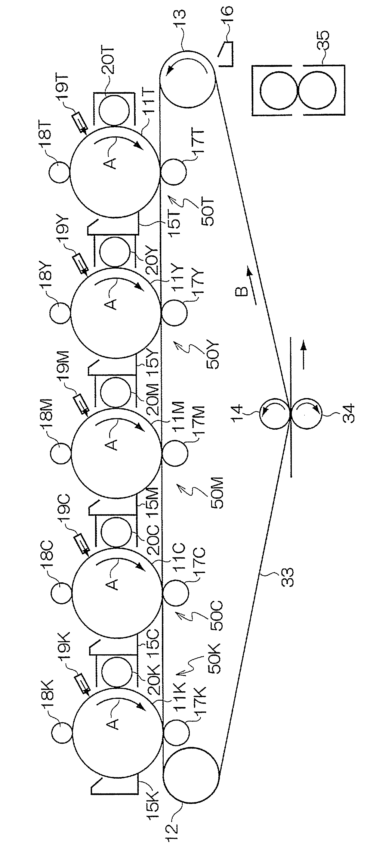
The invention provides a developer for developing an electrostatic latent image, the developer having at least: a transparent toner; and a carrier. The carrier contains at least: a magnetic particle; and a resin coating layer. The resin coating layer coats the surface of the magnetic particle and has cyan color. The invention further provides a developer cartridge storing the developer. The invention further provides a process cartridge storing the developer. The invention further provides an image formation apparatus having at least a color toner image-forming unit, a transparent toner image-forming unit that uses the developer to form a transparent toner image, and a fixing unit.
Description
CROSS-REFERENCE TO RELATED APPLICATION[0001]This application is based on and claims priority under 35 USC 119 from Japanese Patent Application No. 2009-005515 filed on Jan. 14, 2009.BACKGROUND[0002]1. Technical Field[0003]The present invention relates to a developer for developing an electrostatic latent image, a developer cartridge for developing an electrostatic latent image, a process cartridge and an image formation apparatus.[0004]2. Related Art[0005]Methods of visualizing image information through an electrostatic latent image, such as electrophotography, have been used in various fields. In electrophotography, an electrostatic latent image formed on a photoreceptor by charging and exposing is developed with a developer containing a toner, and then is subjected to transferring and fixing to be finally visualized.[0006]Developers that are used in development include a two-component developer containing a toner and a carrier, and a one-component developer which uses a toner alon...
Claims
Login to View More Application Information
Patent Timeline
 Patent Type & AuthorityPatents(United States)
IPC IPC(8): G03G9/00
CPCG03G9/107G03G9/1075G03G9/1133G03G9/1138G03G9/1139G03G15/0131G03G15/0806G03G2215/0602G03G9/1085G03G9/08G03G15/00G03G15/08
InventorMATSUMOTONAKAMURA, YUKIAKI
OwnerFUJIFILM BUSINESS INNOVATION CORP