
Object detection with multiple frequency chirps

a technology of object detection and multiple frequency chirps, applied in the direction of reradiation, measurement devices, instruments, etc., can solve the problems of multi-user interference, inability to suppress others, and neglected important problems such as the resistance to mutual interference, so as to reduce the effect of a single catastrophic interferen

Active Publication Date: 2013-12-03
MITSUBISHI ELECTRIC CORP
View PDF17 Cites 28 Cited by
  • Summary
  • Abstract
  • Description
  • Claims
  • Application Information

AI Technical Summary

Benefits of technology

The invention relates to methods and apparatus for detecting objects using signals with varying frequencies. These methods and apparatus may use a sequence of at least four adjacent portions, where the frequency of the signal varies linearly with time within each portion. The range and speed of the object can be determined based on the received signal and the normalized slopes of the transmitted signal. The technical effects of this invention include improved accuracy and precision in object detection, and reduced interference with other objects. The automotive radar apparatus utilizing this invention can improve safety and reliability in driving.

Problems solved by technology

However, the important problem of resistance to mutual interference has been almost neglected.
It appears that conventional FM patterns and associated signal processing techniques employed in automotive radar can be severely affected by multiuser interference.
Although some forms of interference can be tolerated in a properly designed system, there are others which are impossible to suppress.
Consequently, conventional FM systems operating in dense-signal multiuser environment can only provide inferior obstacle detection and poor estimation of its range and velocity.

Method used


Image

  • Object detection with multiple frequency chirps
  • Object detection with multiple frequency chirps
  • Object detection with multiple frequency chirps

Examples


example 1

Optimal Chirp Sextet

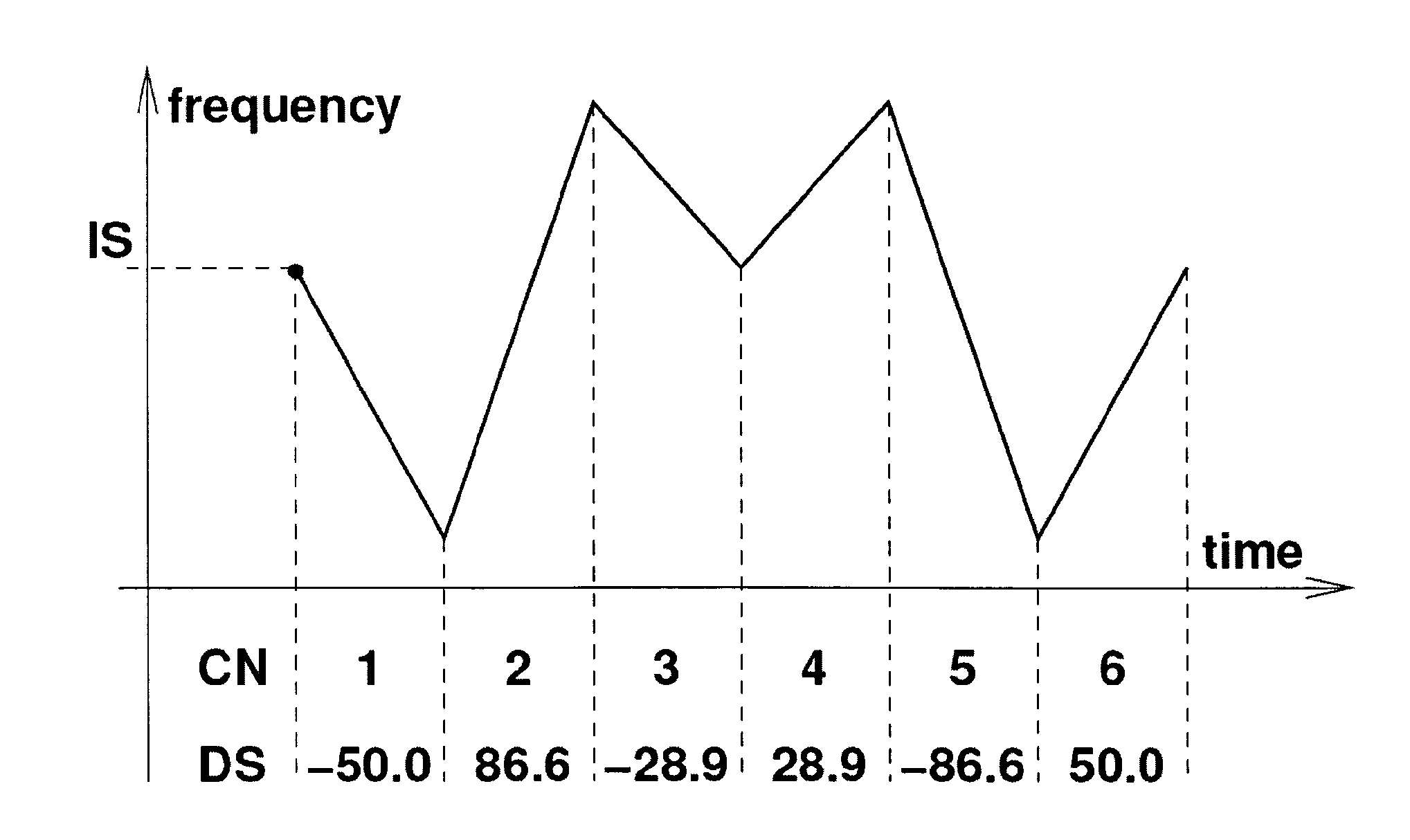
[0103]Assume that it is required to design an advantageous illuminating waveform comprising six frequency chirps. Suppose also that the ratio Z of the maximum slope to the minimum one is given as a design parameter.

[0104]Since six frequency chirps are required, the waveform can be constructed from one chirp quadruple and one chirp doublet. The chirp quadruple is the following quadrichirp

−Z1 / 2,−Z−1 / 2,Z−1 / 2,Z1 / 2.

[0105]When a chirp doublet has been added, the following slope pattern is obtained

−Z1 / 2,−1,−Z−1 / 2,Z−1 / 2,1,Z1 / 2.

[0106]For example, when Z=3, the above slope pattern assumes the form

−√{square root over (3)},−1,−√{square root over (3)} / 3,√{square root over (3)} / 3,1,√{square root over (3)}.

[0107]The inclination angles are the inverse tangents of these values.

[0108]This slope pattern will therefore generate six isobeat lines with the inclination angles

60°,−45°,−30°,30°,45°,60°.

[0109]Although the inclination angles have been expressed in degrees, they could alter...

example 2

Optimal Chirp Octet

[0113]Assume that it is required to design an advantageous illuminating waveform comprising eight frequency chirps. Suppose also that the ratio Z of the maximum slope to the minimum one is given as a design parameter.

[0114]Since eight frequency chirps are required, the waveform can be constructed from two chirp quadruples. A first quadruple is the quadrichirp

−Z1 / 2,−Z−1 / 2,Z−1 / 2,Z1 / 2.

[0115]Although a second quadruple may be just a replica of the above quadrichirp, a second quadruple is advantageously constructed so as to obtain a uniform spread of the inclination angles of the isobeat lines.

[0116]Accordingly, the sector defined by the inclination angles

(tan−1 √{square root over (1 / Z)},tan−1 √{square root over (Z)})=(π / 2−tan−1 √{square root over (Z)},tan−1 √{square root over (Z)})

has to be divided into three equal parts to determine the inclination angles of the two pairs of intermediate isobeat lines. Although the inclination angles have been expressed in radians th...


PUM


Abstract

A system and method are disclosed for the generation and processing of waveforms utilized to modulate the carrier frequency of a microwave sensor employed, to determine the range and velocity of an object of interest. The system and method result in improved performance in environments with high levels of interference.

Description

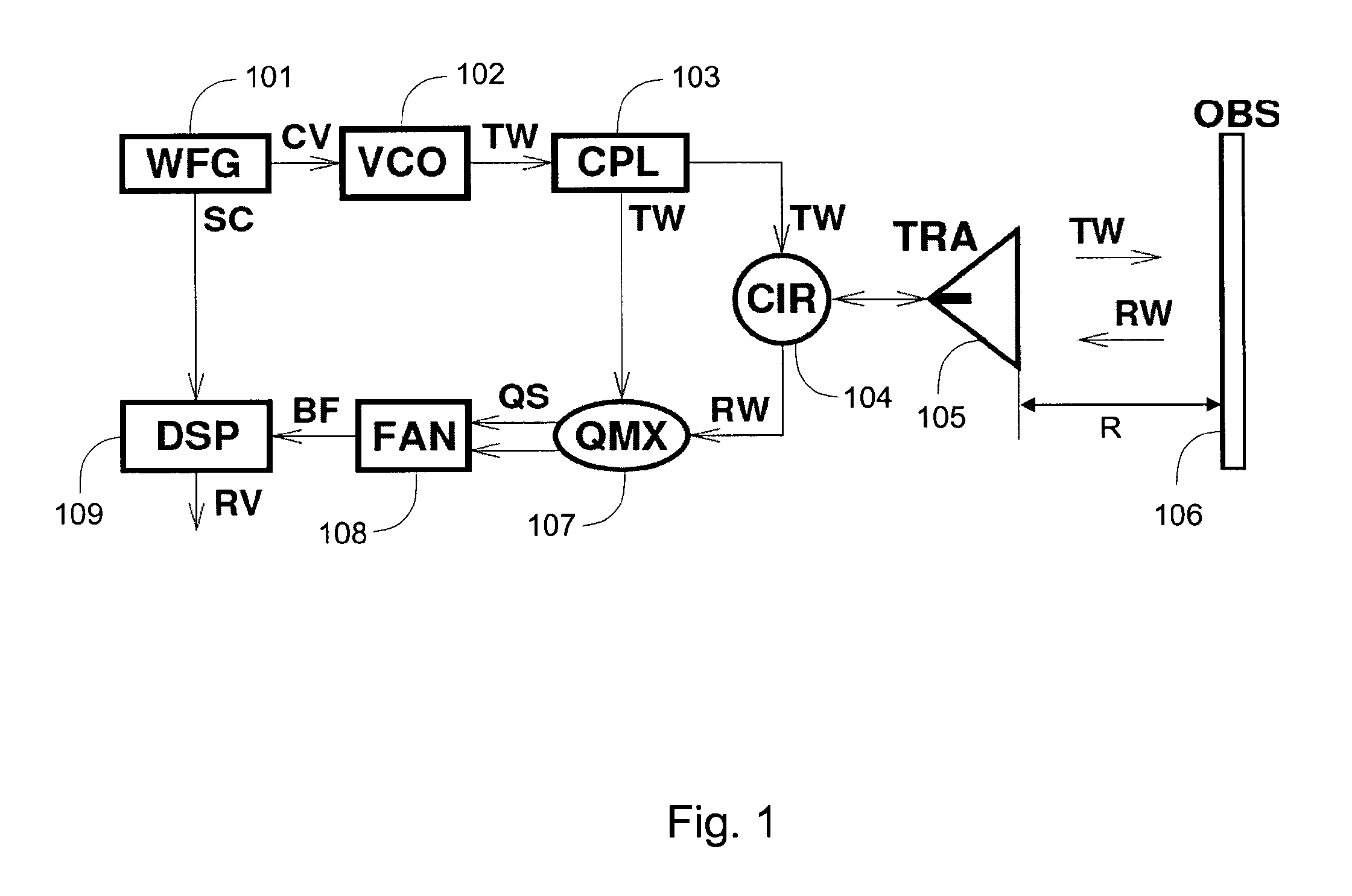
FIELD OF THE INVENTION[0001]This invention relates to a method and apparatus for the generation and processing of waveforms utilized to modulate the carrier frequency of a microwave sensor employed to determine the range and velocity of an object of interest. The method is especially, but not exclusively, applicable to automotive multiuser FMCW radar intended to operate in environments with high level of interference.BACKGROUND OF THE INVENTION[0002]The growing demand for autonomous cruise control and collision warning / avoidance systems has stimulated the development of frequency-modulated continuous-wave (FMCW) automotive radar. Most of the radars under development operate in the 77-GHz band, which has been reserved for these applications.[0003]A functional block diagram of FMCW radar is depicted in FIG. 1. The system comprises a triangular waveform generator WFG 101, a voltage-controlled oscillator VCO 102 acting also as an up-converter, a coupler CPL 103, a circulator CIR 104 to ...

Claims


Application Information

Patent Timeline
Patent Type & Authority Patents(United States)
IPC IPC(8): G01S13/58G01S13/931
CPCG01S7/023G01S13/26G01S13/345G01S13/582G01S13/584G01S13/931
Inventor SZAJNOWSKI, WIESLAW JERZY
Owner MITSUBISHI ELECTRIC CORP
Learn More