
Editing interface

a user interface and editor technology, applied in the field of graphical user interfaces, can solve the problems of inflexibility of many conventional user interfaces, such as those that include physical pushbuttons, and complicated key sequences and menu hierarchies, and achieve the effect of frustrating many users, and reducing the number of users

Active Publication Date: 2013-12-31
APPLE INC
View PDF254 Cites 73 Cited by
  • Summary
  • Abstract
  • Description
  • Claims
  • Application Information

AI Technical Summary

Benefits of technology

The patent describes a method for displaying and exchanging icons on a touch-sensitive display of a portable electronic device. By receiving user input, the device can modify the visual appearance of an icon and display it in a different position in the user interface. This allows for easier selection and movement of icons, improving the overall user experience.

Problems solved by technology

As portable devices become more compact, and the amount of information to be processed and stored increases, it has become a significant challenge to design a user interface that allows users to easily interact with the device.
This is unfortunate since the user interface is the gateway through which users receive not only content but also responses to user actions or behaviors, including user attempts to access a device's features or tools.
These conventional user interfaces often result in complicated key sequences and menu hierarchies that must be memorized by the user.
Many conventional user interfaces, such as those that include physical pushbuttons, are also inflexible.
This is unfortunate because the inflexibility may prevent a user interface from being configured and / or adapted by either an application running on the portable device or by users.
When coupled with the time consuming requirement to memorize multiple key sequences and / or menu hierarchies, such inflexibility is frustrating to many users.
Unfortunately, the process of modifying such conventional user interfaces is often as cumbersome and complicated as the use of the conventional user interface itself.
In particular, the required behaviors during configuration of such conventional user interfaces are often counter intuitive and the corresponding indicators guiding user actions are often difficult to understand.
These challenges are often a source of additional frustration for users.

Method used


Image

  • Editing interface
  • Editing interface
  • Editing interface

Examples


Embodiment Construction

[0020]Reference will now be made in detail to embodiments, examples of which are illustrated in the accompanying drawings. In the following detailed description, numerous specific details are set forth in order to provide a thorough understanding of the present invention. However, it will be apparent to one of ordinary skill in the art that the present invention may be practiced without these specific details. In other instances, well-known methods, procedures, components, and circuits have not been described in detail so as not to unnecessarily obscure aspects of the embodiments.

Overview of the Interface Reconfiguration Mode

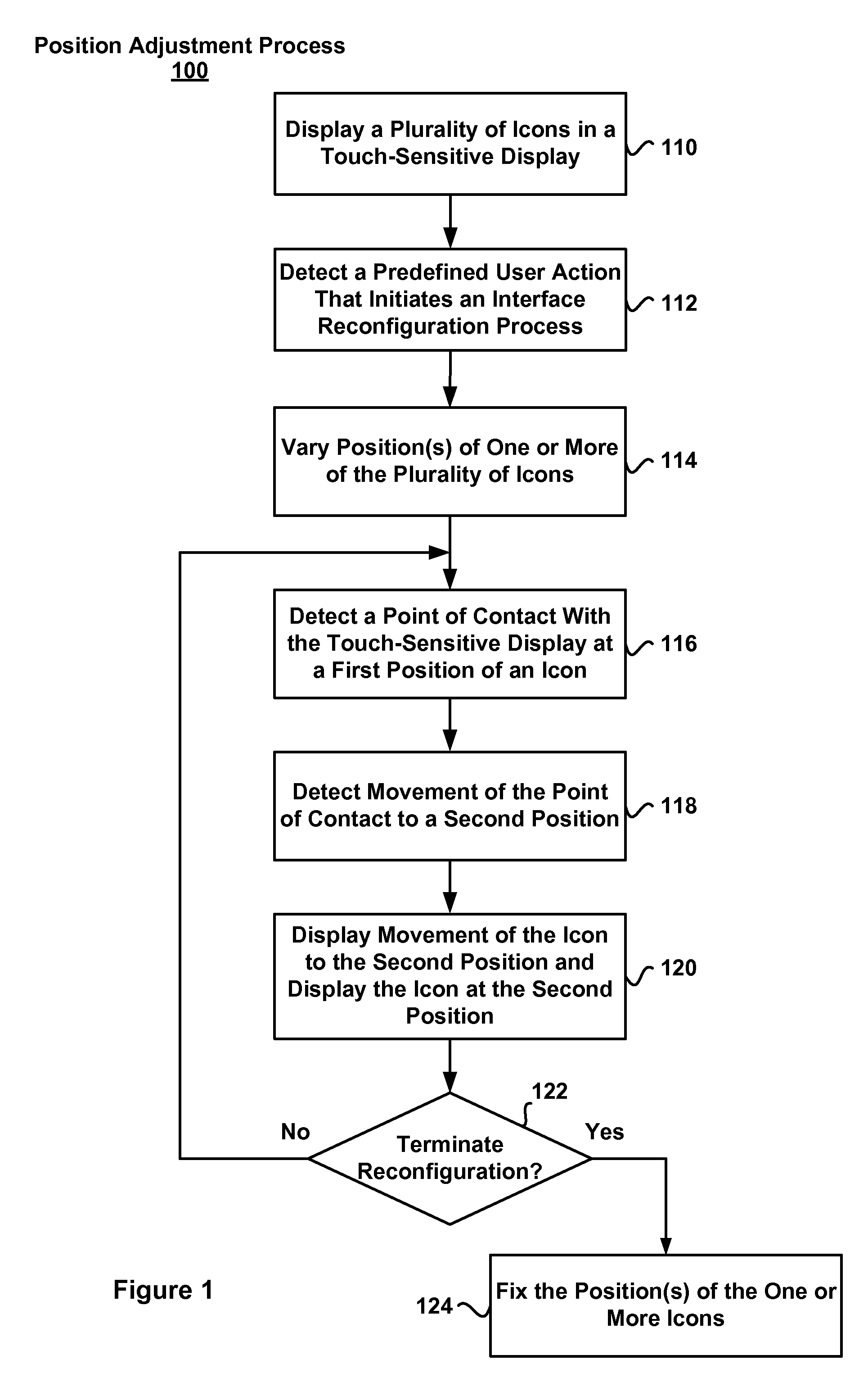
[0021]Attention is directed towards embodiments of portable electronic devices, including portable communications devices, that have graphical user interfaces (GUIs). The portable devices include an interface reconfiguration mode. In response to a user initiating the interface reconfiguration mode, positions of one or more icons displayed on the portable device ...


PUM


Abstract

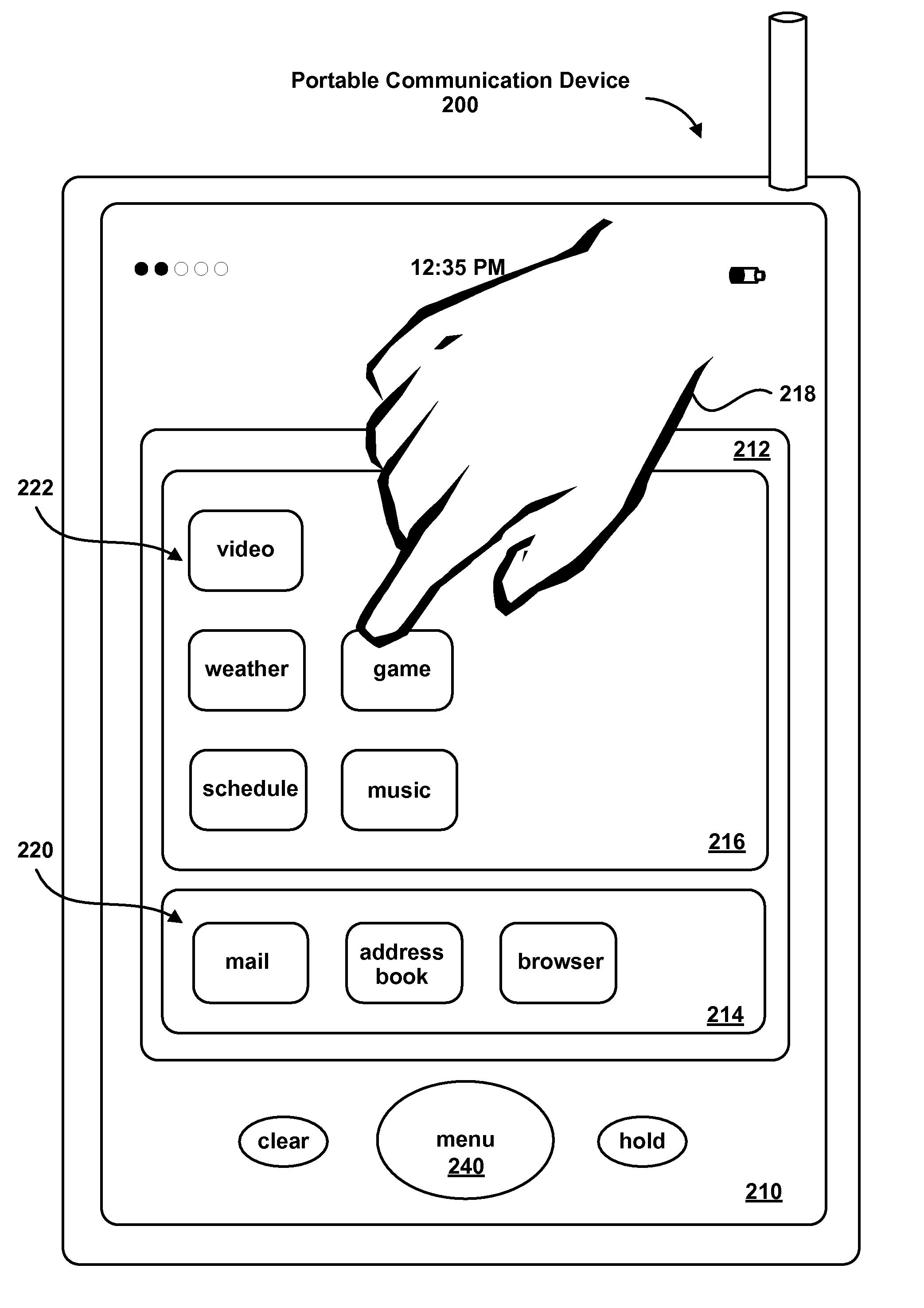
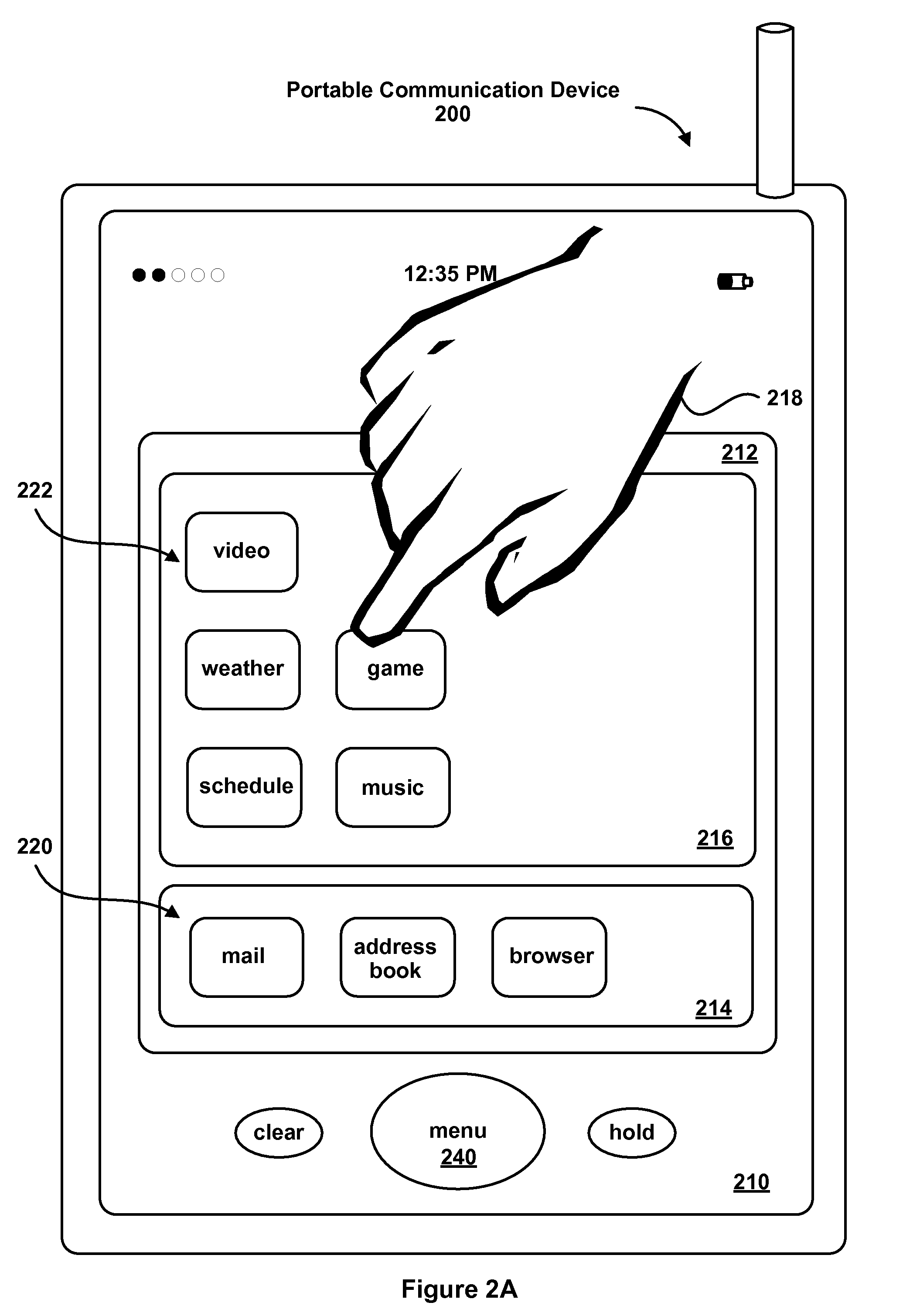
A portable electronic device displays icons (e.g., graphical objects) in one or more regions of a user interface of a touch-sensitive display, and detects user input specifying an exchange of positions of icons in the user interface. In some aspects, the respective positions of two icons in a user interface can be selected to exchange positions in the one or more regions of the user interface, and one or both icons can change their visual appearance to indicate their selection status.

Description

TECHNICAL FIELD[0001]The disclosed embodiments relate to graphical user interfaces.BACKGROUND[0002]As portable devices become more compact, and the amount of information to be processed and stored increases, it has become a significant challenge to design a user interface that allows users to easily interact with the device. This is unfortunate since the user interface is the gateway through which users receive not only content but also responses to user actions or behaviors, including user attempts to access a device's features or tools. Some portable electronic devices (e.g., mobile phones) have resorted to adding more pushbuttons, overloading the functions of pushbuttons, or using complex menu systems to allow a user to access, store and manipulate functions or data. These conventional user interfaces often result in complicated key sequences and menu hierarchies that must be memorized by the user.[0003]Many conventional user interfaces, such as those that include physical pushbu...

Claims


Application Information

Patent Timeline
Patent Type & Authority Patents(United States)
IPC IPC(8): G06F3/0486
CPCG06F3/0488G06F3/04847G06F3/04817G06F3/016G06F3/04842G06F3/0486G06F3/0482G06F3/041
Inventor CHAUDHRI, IMRAN A.ORDING, BASJOBS, STEVEN
Owner APPLE INC
Learn More