Inertial sensor cluster and sensor system

a sensor cluster and sensor technology, applied in the field of sensor devices, can solve the problems of disadvantageously large installation space and relatively high manufacturing cost, and achieve the effect of flexible use, flexible positioning, and particularly flexible and comfortable us

Active Publication Date: 2014-02-11
ROBERT BOSCH GMBH
View PDF3 Cites 7 Cited by
  • Summary
  • Abstract
  • Description
  • Claims
  • Application Information

AI Technical Summary

Benefits of technology

[0007]The sensor device according to the present invention has the advantage over the related art that the sensor device has a first and a second sensor module, the first sensor module being enclosed by a first medium, and the second sensor module being enclosed by a second medium, so that it is advantageously possible to highly flexibly adapt the first and the second media to the requirements of the first and the second modules, respectively, and to thus achieve a particularly reliable and interference-resistant sensor device which includes different sensor types. For example, it is preferably possible to simultaneously accommodate a yaw-rate sensor for chassis regulation and a crash sensor for recognizing an accident situation in only one sensor device; a particularly reliable and interference-free operation of both sensor types may be ensured by appropriately selecting the first and the second media. Preferably, the first and the second media essentially entirely fill out the particular area between the outer shell and the first and the second sensor modules, so that a mechanically stable fixing of the first and the second sensor modules may be implemented simultaneously with the aid of the first and the second media, and other fixing elements, which are mostly complicated to manufacture, may be dispensed with. Furthermore, the first and the second media offer a protective function against mechanical shocks and vibrations. Additionally, the sensor device according to the present invention may be implemented in a particularly compact and cost-effective manner and may thus be advantageously used, in particular in automobile manufacture. For example, a plurality of such sensor devices may be placed in an automobile in this way at relatively low cost, in order to generate several redundant measuring signals and to thus minimize the susceptibility to failure of a sensor system in an automobile.
[0008]According to a preferred refinement, it is provided that the first medium includes a first volume-compressible material and / or that the second medium includes a second volume-compressible material. In particular, it is preferred according to the present invention that the first and / or the second medium has / have a frequency-filter behavior and preferably function(s) as a low-pass filter. This makes it advantageously possible to damp higher-frequency interference signals coupled into the sensor device and to thus also suppress or essentially completely avoid resonance exaggerations of the measuring signal, which significantly increases the accuracy of a yaw-rate measurement, for example, when a yaw-rate sensor is used. It is preferred according to the present invention that the first volume-compressible material has a lower compressibility than the second volume-compressible material. For this reason, it is conceivable, for example, that the first material is volume-elastic only lightly or essentially not at all, so that force effects on the outer casing of the sensor device are transmitted essentially undamped on the first sensor module as it is advantageous in the case of a crash sensor for detecting high-frequency acceleration signals. Preferably, the first and / or the second material is / are an elastomer which contains gas bubbles, the compressibility of the elastomer being advantageously adjustable within a manufacturing process via the volume fraction of the gas bubbles. Depending on the desired compressibility and the damping properties associated with it, the volume fraction of the gas bubbles preferably ranges between 0.5% and 30%. In this way, it is advantageously possible according to the present invention to optimize the compressibility of the first and the second media with regard to the damping properties required for the particular sensor type with the aid of a relatively simple and cost-effective manufacturing method, and to thus make available a particularly reliably performing sensor device.
[0009]According to one preferred refinement, it is provided that the first sensor module and the second sensor module are electrically conductively connected to only one single contact element for supplying power and transmitting signals, the contact element having only two electrically isolated electrical contact parts, in particular two connection pins. Preferably, the electrical contact parts are at least partially accessible from the outside of the outer casing. The electrical contact parts are particularly preferably implemented, at least in a subarea, as plug contacts for conventionally available plugs, so that a particularly simple electrical connection to the sensor device is possible. By using only two electrical contact parts, it is advantageously possible to use particularly small plugs for the connection to the sensor device, whereby the installation space requirement of the sensor device according to the present invention may particularly advantageously be reduced. Furthermore, it is preferred according to the present invention that the contact element is made of a continuous metal part manufactured with the aid of a punching technique and is thus manufacturable particularly cost-effectively. While sensor modules in the related art are mostly situated on a relatively bulky printed board, the sensor device according to the present invention has the advantage that the first and / or the second sensor module(s) is / are directly connected to the contact element, thus allowing for a particularly compact sensor device with regard to installation space, a high mechanical stability being furthermore ensured by enclosing the first and the second sensor modules in a first and a second media.

Problems solved by technology

In order to meet these various demands, different sensor types have each hitherto been placed in a separate casing, thus requiring a disadvantageously great installation space and incurring relatively high manufacturing costs.

Method used


Image

  • Inertial sensor cluster and sensor system
  • Inertial sensor cluster and sensor system
  • Inertial sensor cluster and sensor system

Examples


Embodiment Construction

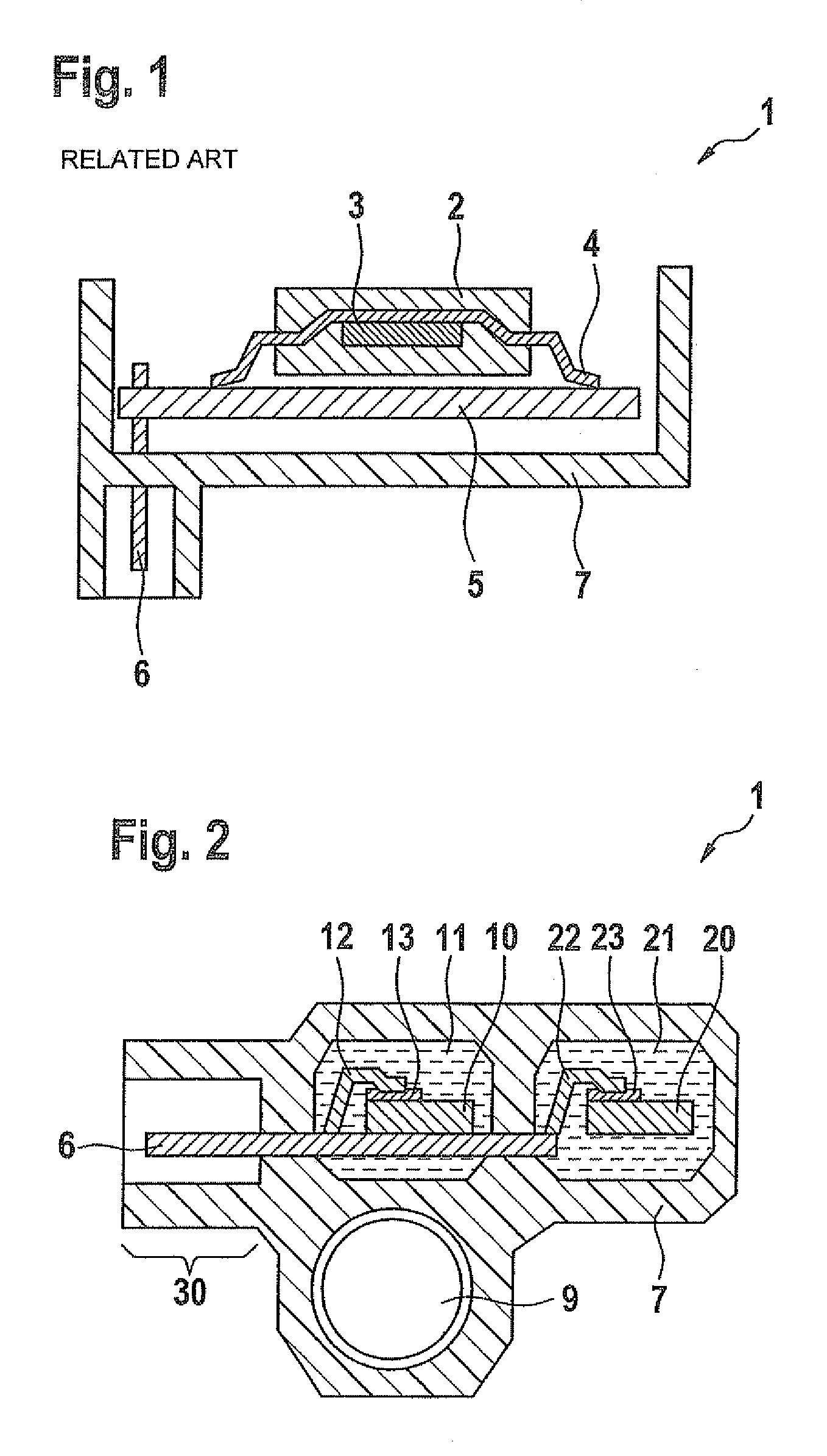
[0021]FIG. 1 schematically shows a cross section of a sensor device 1 according to the related art, sensor device 1 including a sensor module 2 having a sensor element 3, sensor module 2 being situated on a printed board 5, sensor module 2 being electrically conductively connected to printed board 5 via a connecting element 4, e.g., a carrier strip, printed board 5 being electrically conductively connected to a contact element 6 and being fixed on an outer casing 7. Outer casing 7 includes sensor module 2 at least partially or preferably entirely, so that adequate protection of sensor module 2 is ensured. Contact element 6 usually includes multiple connection pins for supplying sensor module 2 with power and for reading out the measuring signals. Furthermore, contact element 6 is accessible at least partially from the outside and allows a conventional plug to be connected, for example.

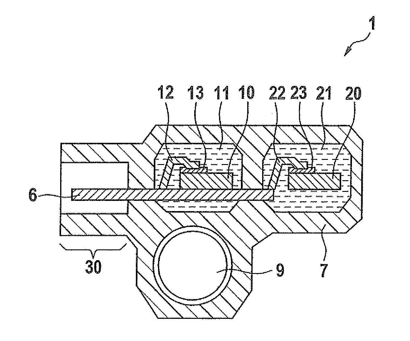
[0022]FIG. 2 schematically shows a cross section of a preferred specific embodiment of sensor devic...


PUM


Abstract

A sensor device includes an outer casing, a first sensor module and a second sensor module. The outer casing encloses the first sensor module and the second sensor module at least partially. The first sensor module is enclosed at least partially by a first medium, and the second sensor module is enclosed at least partially by a second medium.

Description

BACKGROUND OF THE INVENTION[0001]1. Field of the Invention[0002]The present invention is directed to a sensor device having at least two sensor modules.[0003]2. Description of the Related Art[0004]Sensor devices have been used in vehicles for many years for detecting the vehicle kinematics and make it possible to regulate the operating dynamics of a vehicle (e.g., in ESP systems) or to control the safety functions of the vehicle, such as triggering the airbag. Such sensor devices must meet high demands with regard to their susceptibility to failure and reliability.[0005]For example, published German patent application document DE 10 2007 057 441 A discloses a sensor device having a sensor module situated on a printed board, the sensor module being essentially entirely enclosed in a volume-elastic medium, the volume-elastic medium having a low-pass behavior. The low-pass behavior advantageously allows the coupling of higher-frequency interference signals in the sensor device to be su...

Claims


Application Information

Patent Timeline
Patent Type & Authority Patents(United States)
IPC IPC(8): G01P1/02
CPCG01D11/245
Inventor OHL, CHRISTIANULLMANN, DIRK
Owner ROBERT BOSCH GMBH
Why Eureka
Try Eureka