Turbo-compressor device

A turbo compressor and internal space technology, applied in the direction of pump devices, components of pumping devices for elastic fluids, mechanical equipment, etc., can solve the problems of expensive, complex components, high dissipation losses, etc., and achieve small supporting force , The effect of small rotor dynamic performance

Inactive Publication Date: 2004-06-16
MAN ENERGY SOLUTIONS SE
View PDF1 Cites 1 Cited by
  • Summary
  • Abstract
  • Description
  • Claims
  • Application Information

AI Technical Summary

Problems solved by technology

The disadvantage of this embodiment is that the assembly is very expensive and complex; this arrangement is at most suitable for two-stage radial turbocompressors; this turbocompressor arrangement has high dissipative losses

Method used


Image

  • Turbo-compressor device
  • Turbo-compressor device
  • Turbo-compressor device

Examples


Embodiment Construction

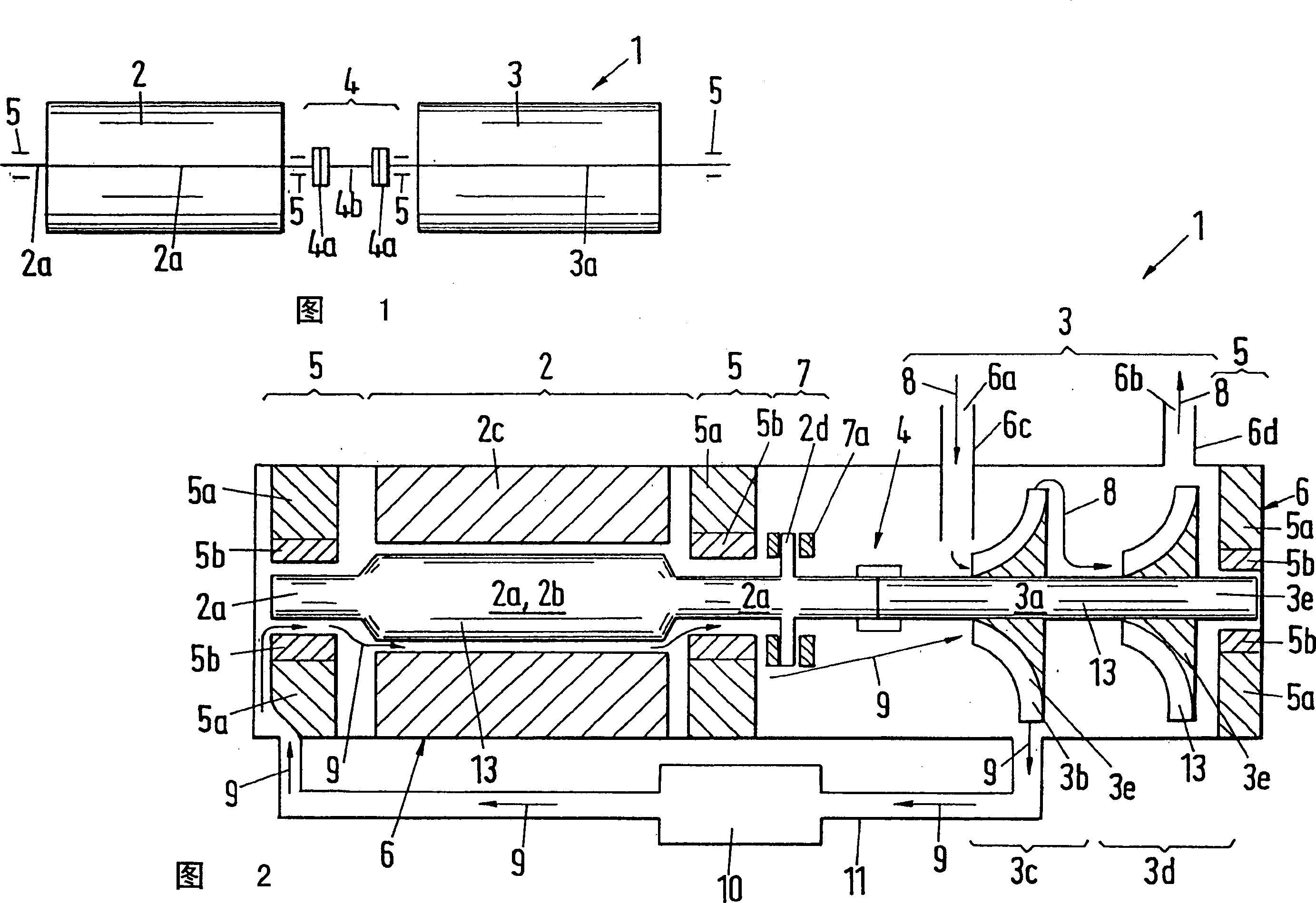
[0035] FIG. 1 schematically shows a known turbocompressor 1 comprising a radial turbocompressor 3 with a shaft 3a and a drive motor 2 with a shaft 2a. The shaft 3 a of the radial turbo compressor 3 is journalled at both ends by two radial bearings 5 ​​. The shaft 3 a of the electric machine 2 is likewise journaled at both ends by two radial bearings 5 ​​. The two shafts 2a and 3a are connected to each other through a connector 4, the connector 4 includes two connecting parts 4a and a flexible intermediate piece 4b, so that the motor 2 drives the radial turbo compressor 3 through the shaft 2a and the connector 4 Axis 3a.

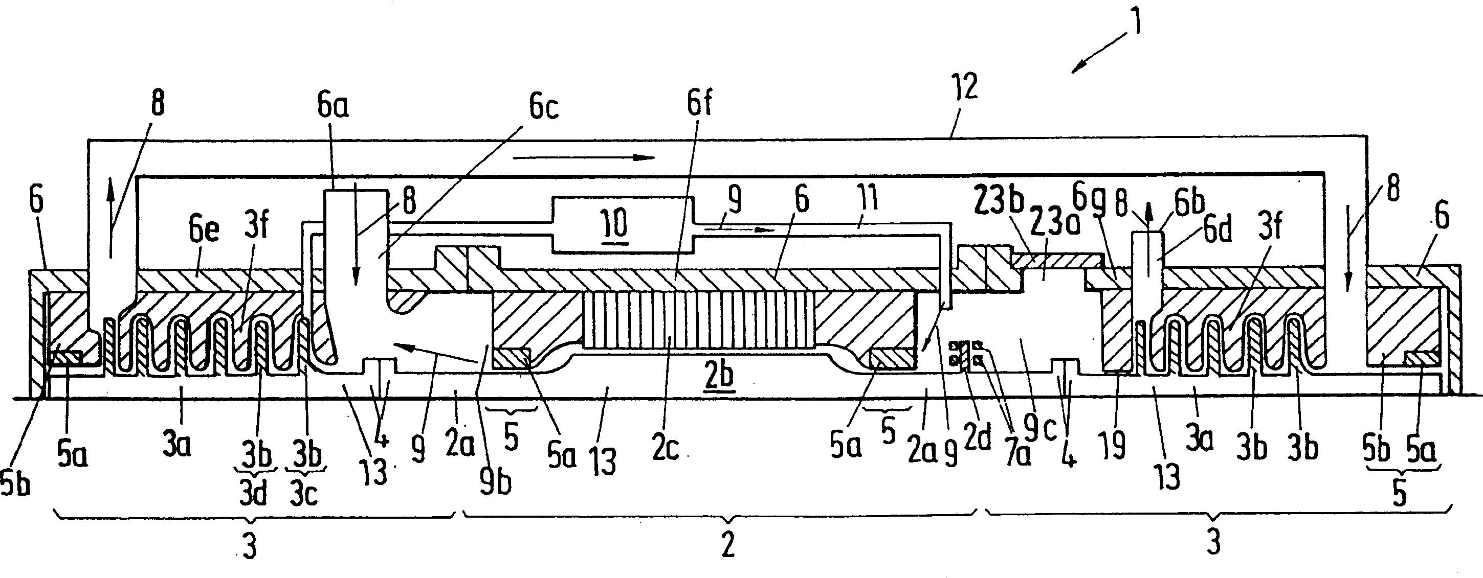
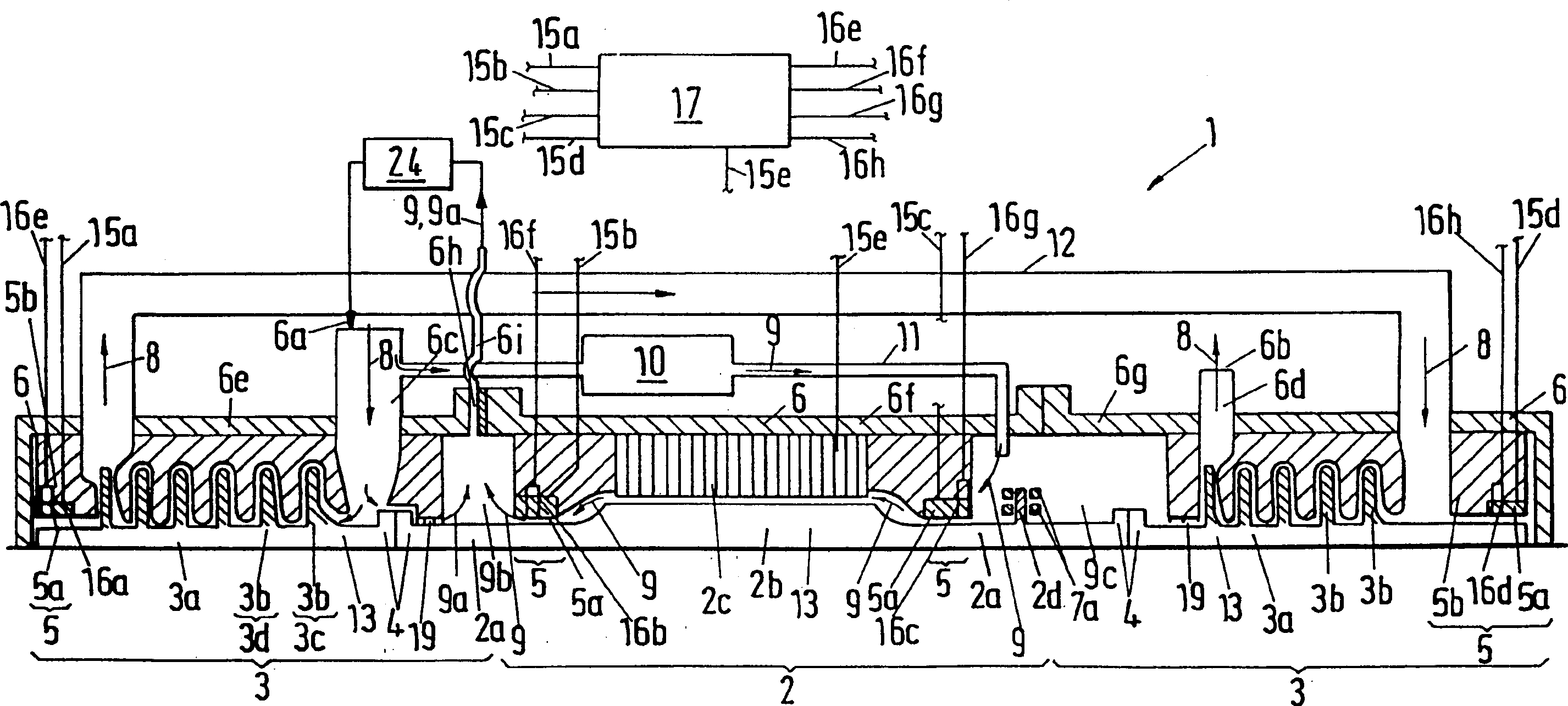
[0036] Fig. 2 shows a turbocompressor device 1, which is arranged in a sealed pressure-resistant casing 6, the pressure-resistant casing 6 is provided with an inlet pipe 6c and an outlet pipe 6b, both pipes lead into the pressure-resistant casing 6 , so that the radial turbocompressor 3 is fluidically connected to a device arranged outside the pressure-resi...


PUM


Abstract

A turbocompressor (1) has an outwardly gas-tight housing (6) within which an electric motor (2) and a multistage radial turbocompressor (3) are arranged on a common shaft (13). For journalling the shaft (13), electromagnetic radial bearings (5) are arranged spaced apart in the direction of the shaft. A gas seal (19) surrounding the shaft (13) is arranged between the electric motor (2) and the radial turbocompressor (3) in order to seal off the electric motor (2) with respect to the radial turbocompressor (3). The electric motor (2) has an inner space (9b, 9c) which is connected in a fluid-conducting manner to an outlet opening which passes through the housing (6).

Description

technical field [0001] The invention relates to a turbo compressor device. Background technique [0002] A known turbo compressor unit comprises a radial turbo compressor and an electric motor, each of these units is arranged in a separate housing, the shaft of the electric motor is connected to the radial turbo compressor via a flexible shaft portion. [0003] A disadvantage of this known turbocompressor arrangement is that it is rather large in design, requires several seals and bearings, and therefore the turbocompressor arrangement is expensive to manufacture. [0004] Patent document DE2729486C1 discloses a turbocompressor device in FIG. 1, which includes a two-stage radial turbocompressor and also includes a motor, both of which are connected to a rigid shaft, which is used in three positions Magnetic radial bearing journal support. The disadvantage of this embodiment is that the assembly is very expensive and complex; this arrangement is suitable for at most two-sta...

Claims


Application Information

Patent Timeline
IPC IPC(8): F04D29/056F04B3/00F04B17/00F04B17/03F04B35/00F04B35/02F04D1/06F04D13/06F04D17/12F04D17/16F04D25/02F04D25/06F04D29/04F04D29/058F04D29/10F04D29/12F04D29/28F04D29/44F04D29/58
CPCF04D25/0606F04D29/058F04D29/584F04D17/12F04D25/0686F04D29/5806
Inventor D·格洛布J·-C·普拉德托D·德斯布尔格
Owner MAN ENERGY SOLUTIONS SE
Why Eureka
Try Eureka