Apparatus and methods for Z-axis control and collision detection and recovery for waterjet cutting systems

a technology of z-axis control and cutting system, which is applied in the direction of grinding machine components, metal-working machine components, manufacturing tools, etc., can solve the problems of system shutdown and possibly a damaged workpiece, mixing tubes are relatively expensive components of the cutting head, and the cutting head is relatively expensive. , to achieve the effect of preventing the cutting head from breaking, reducing the support force, and reducing the cost of the cutting head

Inactive Publication Date: 2005-02-08
FLOW INT
View PDF35 Cites 35 Cited by
  • Summary
  • Abstract
  • Description
  • Claims
  • Application Information

AI Technical Summary

Benefits of technology

In another aspect, an apparatus according to the invention includes a first mount member coupleable to a controllably positionable mounting surface of the waterjet cutting system, a second mount member coupleable to the cutting head and disengageably coupled to the first mount member, and a sensing circuit having a plurality of first conductive elements disposed on the first mount member and a plurality of second conductive elements disposed on the second mount member. In the event of a collision between the cutting head and an obstruction, the second mount member disengages from the first mount member to prevent breakage of the cutting head. Following the collision, the second mount member is quickly and easily re-engaged with the first mount member without time-consuming re-calibration. In one embodiment, re-engagement of the second and first mount members is automatically performed by a biasing member.
In another aspect, a method of controlling a height of a cutting head of a waterjet cutting system over a surface of a workpiece includes coupling a first end of a contact member to the cutting head, engaging a second end of the contact member with the surface of the workpiece, providing an adjustably controllable support force to support a weight of the cutting head, and slightly reducing the support force to slightly downwardly bias the contact member into engagement with the surface of the workpiece. The position control method advantageously provides a simple height measurement system and also allows for automatic adjustment for changes in friction or weight of various components of the waterjet cutting system.

Problems solved by technology

If the standoff distance d is to close, the mixing tube 26 can plug during piercing, causing system shutdown and possibly a damaged workpiece 12.
If the distance is too far, the quality and accuracy of the cut suffers.
Thus, mixing tubes are a relatively expensive component of the cutting head 20.
The specially formulated carbides are also quite brittle, and can easily break if the mixing tube 26 collides with an obstruction during operation of the cutting system 10, such as fixturing or cut-out portions of the workpiece 12 which have been kicked up during the cutting operation.
Accidental breakage of the mixing tube 26 increases operational costs and downtime of the cutting system 10.
A fundamental problem with such collision sensors is that they must have a large enough “safety buffer” between the sensor and a mixing tube to allow the control gantry enough time to stop without damaging the mixing tube.
Due to the size and speed of modem cutting systems, the task of stopping the control gantry quickly to avoid a collision is quite difficult.
Another problem is that any shifting of the components requires a lengthy re-calibration routine to insure proper standoff distance d. A serious collision can ruin the ring sensor.
This approach, however, prevents the cutting jet 16 from cutting near obstructions and fixtures commonly found around the edges of the workpiece 12, thereby wasting material.
Enlarging the ring also increases the occurrence of erroneous collision signals which results in unnecessary downtime of the cutting system.
Finally, existing ring sensor devices are expensive and are not robust in detecting surface height or collisions when operating the control gantry at high-speed or under dirty conditions.

Method used


Image

  • Apparatus and methods for Z-axis control and collision detection and recovery for waterjet cutting systems
  • Apparatus and methods for Z-axis control and collision detection and recovery for waterjet cutting systems
  • Apparatus and methods for Z-axis control and collision detection and recovery for waterjet cutting systems

Examples


Embodiment Construction

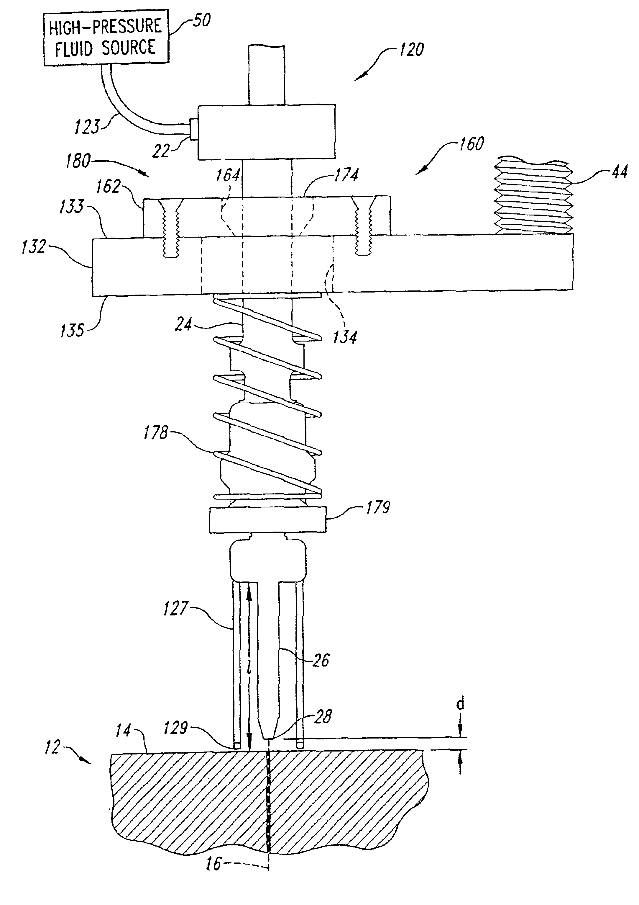
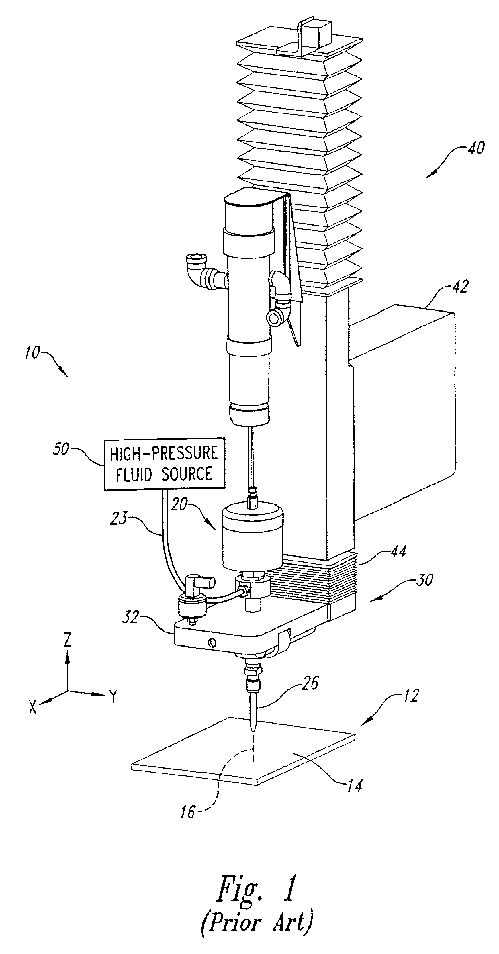
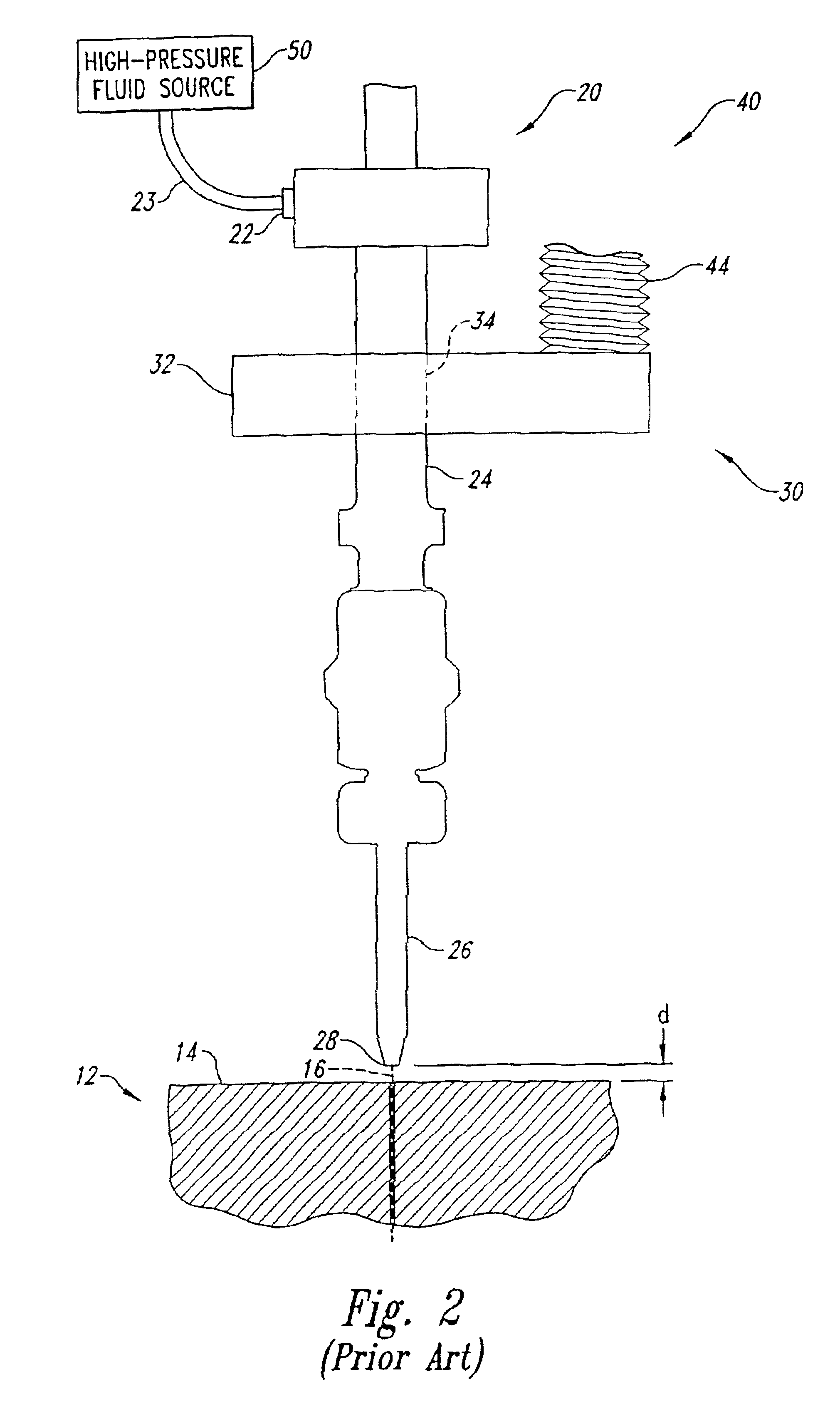
The present disclosure is directed toward apparatus and methods for z-axis control and collision detection and recovery of cutting heads of waterjet cutting systems. Specific details of certain embodiments of the invention are set forth in the following description, and in FIGS. 3-9 to provide a thorough understanding of such embodiments. A person of ordinary skill in the art, however, will understand that the present invention may have additional embodiments, and that the invention may be practiced without several of the details described in the following description.

FIG. 3 is an isometric view of a waterjet cutting system 100 in accordance with an embodiment of the invention. The waterjet cutting system 100 includes a cutting head 120 coupled to a disengageable (or “breakaway”) mounting assembly 160. In the event of a collision, the disengageable mounting assembly 160 advantageously disengages (or “breaks”) to prevent breakage of the mixing tube 26 or other cutting head components...


PUM

PropertyMeasurementUnit
pressureaaaaaaaaaa
angleaaaaaaaaaa
volumeaaaaaaaaaa

Abstract

This invention relates to apparatus and methods for z-axis control and collision detection and recovery for waterjet and abrasive-jet cutting systems. In one embodiment, an apparatus includes a linear rail, a slide member coupleable to a cutting head and slideably coupled to the linear rail, at least one actuator having a first end coupled to the slide member and a second end fixed with respect to the linear rail, a position sensor, and a controller. The actuator provides an adjustable support force that supports the weight of the cutting head, allowing the cutting head to be controllably positioned at a desired height above the workpiece. The actuator may include a pneumatic cylinder, or alternately, a linear motor. In another aspect, an apparatus includes a first mount member coupleable to a controllably positionable mounting surface of the waterjet cutting system, a second mount member coupleable to the cutting head and disengageably coupled to the first mount member, and a sensing circuit having a plurality of first conductive elements disposed on the first mount member and a plurality of second conductive elements disposed on the second mount member. In the event of a collision between the cutting head and an obstruction, the second mount member disengages from the first mount member to prevent breakage of the cutting head. Following the collision, the second mount member is quickly and easily re-engaged with the first mount member without time-consuming re-calibration. In one embodiment, re-engagement of the second end first mount members is automatically performed by a biasing member.

Description

TECHNICAL FIELDThis invention relates to apparatus and methods for z-axis control and collision detection and recovery for waterjet and abrasive-jet cutting systems.BACKGROUND OF THE INVENTIONWaterjet and abrasive-jet cutting systems are used for cutting a wide variety of materials. In a typical waterjet cutting system, a high-pressure fluid (e.g., water) flows through a cutting head having a cutting nozzle that directs a cutting jet onto a workpiece. The cutting nozzle may include a mixing tube for introducing an abrasive into the high-pressure cutting jet to form an abrasive cutting jet. The cutting nozzle may then be controllably moved across the workpiece to cut the workpiece into the desired shape. After the cutting jet (or abrasive cutting jet) passes through the workpiece, the energy of the cutting jet is dissipated and the fluid is collected in a catcher tank for disposal. Waterjet and abrasive jet cutting systems of this type are shown and described, for example, in U.S. Pa...

Claims


Application Information

Patent Timeline
Patent Type & Authority Patents(United States)
IPC IPC(8): B23Q17/00B23Q5/00B23Q11/04B23Q11/06B23Q5/58B24C1/04B24C1/00B26D7/22B26D7/24B26D7/00B26F3/00
CPCB23Q5/58B23Q11/04B23Q17/005B26F3/004B26D7/22B26D7/24B24C1/045Y10T83/096Y10T83/145Y10T83/0591Y10T83/364Y10T83/0443
Inventor STEWART, JONATHAN M.PESEK, THOMASKERN, VOLKERWU, CHIEN CHOUCHIN, DANIELSCIULLI, FELICE M.
Owner FLOW INT
Why Eureka
Try Eureka