
Exoskeleton and method of using the same

a technology of exoskeleton and wearable structure, which is applied in the field of exoskeleton and other wearable structures, can solve the problems of not allowing for flexibility of legs, and often carrying heavy loads, and achieves the effect of reducing the support of load

Active Publication Date: 2015-12-24
MAWASHI PROTECTIVE CLOTHING
View PDF0 Cites 31 Cited by
  • Summary
  • Abstract
  • Description
  • Claims
  • Application Information

AI Technical Summary

Benefits of technology

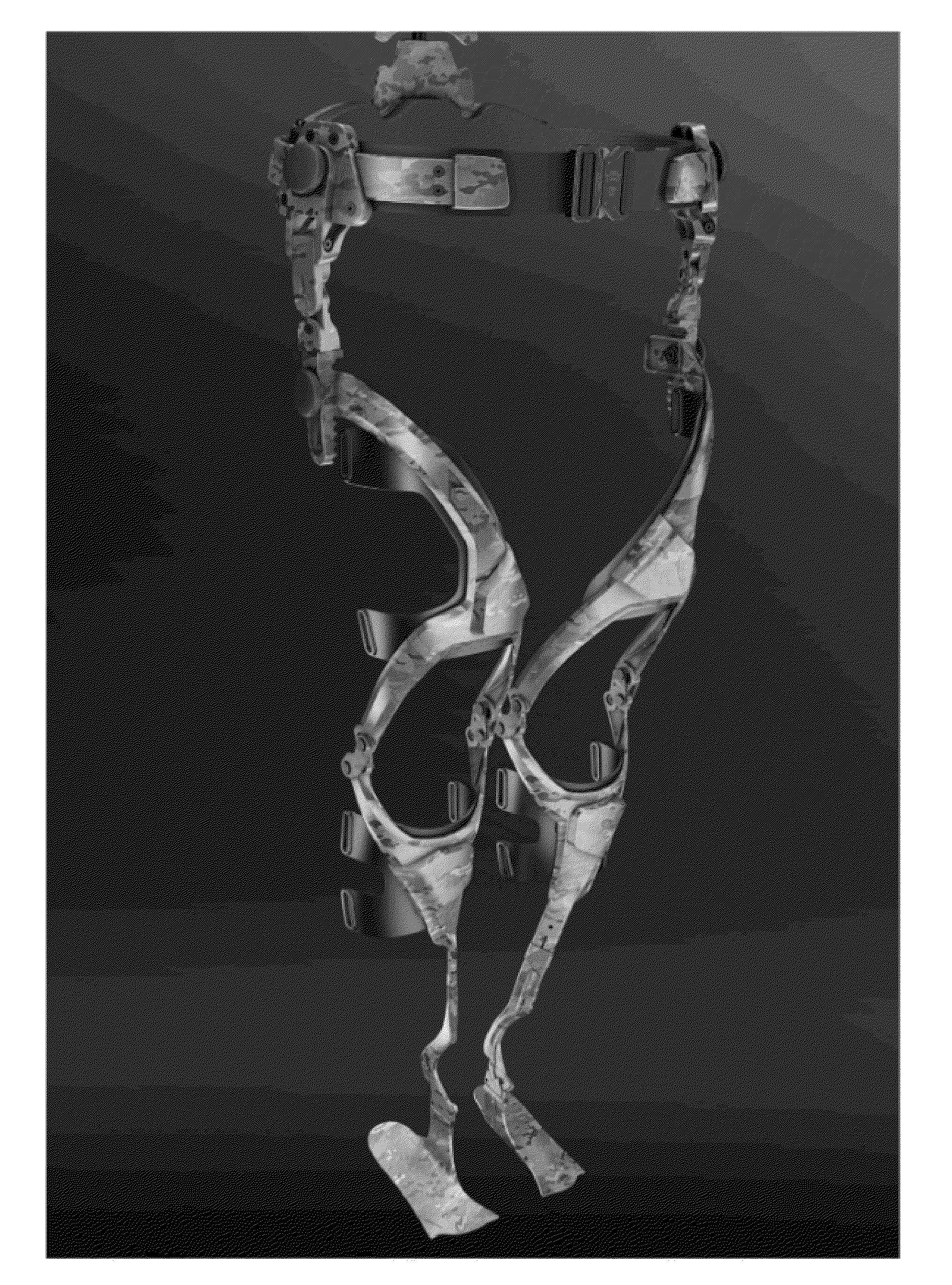
The present invention is an exoskeleton that helps users carry loads more easily and comfortably. It is designed to transfer the load from the user's hips to the inside of their legs, which aligns with human biomechanics. This exoskeleton can be worn by various users, such as soldiers, firefighters, and hikers, to assist them in carrying loads. Overall, the invention improves the efficiency and comfort of load carrying for users.

Problems solved by technology

For example, soldiers in the field, firefighters, police officers, antiriot squads, but also construction workers, and hikers, are often faced with the problem of carrying heavy loads, sometimes over long distances.
However, such arrangement does not allow for flexibility of the legs, when the user often needs to be able to squat.
While useful, such a configuration does not provide for easy manipulation of a load by the wearer over a long distance.
Additionally, such a device does not address the problem of unequal weight distribution about an exoskeleton trunk, which could cause significant balancing problems for a wearer of the exoskeleton, while the wearer is stationary as well as walking.
Therefore, most of the prior art consists of powered exoskeletons, which, although useful in certain circumstances, may be inadequate, due to the excess weight, costs, dependence on power supply, and lack of ergonomic mobility for the user.
Furthermore, most of the prior art consists of exoskeletons which have their load bearing design directed on the outside of the leg, which is not compatible with the human biomechanics and which may cause serious injuries to the user.

Method used


Image

  • Exoskeleton and method of using the same
  • Exoskeleton and method of using the same
  • Exoskeleton and method of using the same

Examples


Embodiment Construction

[0051]A novel load carriage exoskeleton will be described hereinafter. Although the invention is described in terms of specific illustrative embodiments, it is to be understood that the embodiments described herein are by way of example only and that the scope of the invention is not intended to be limited thereby.

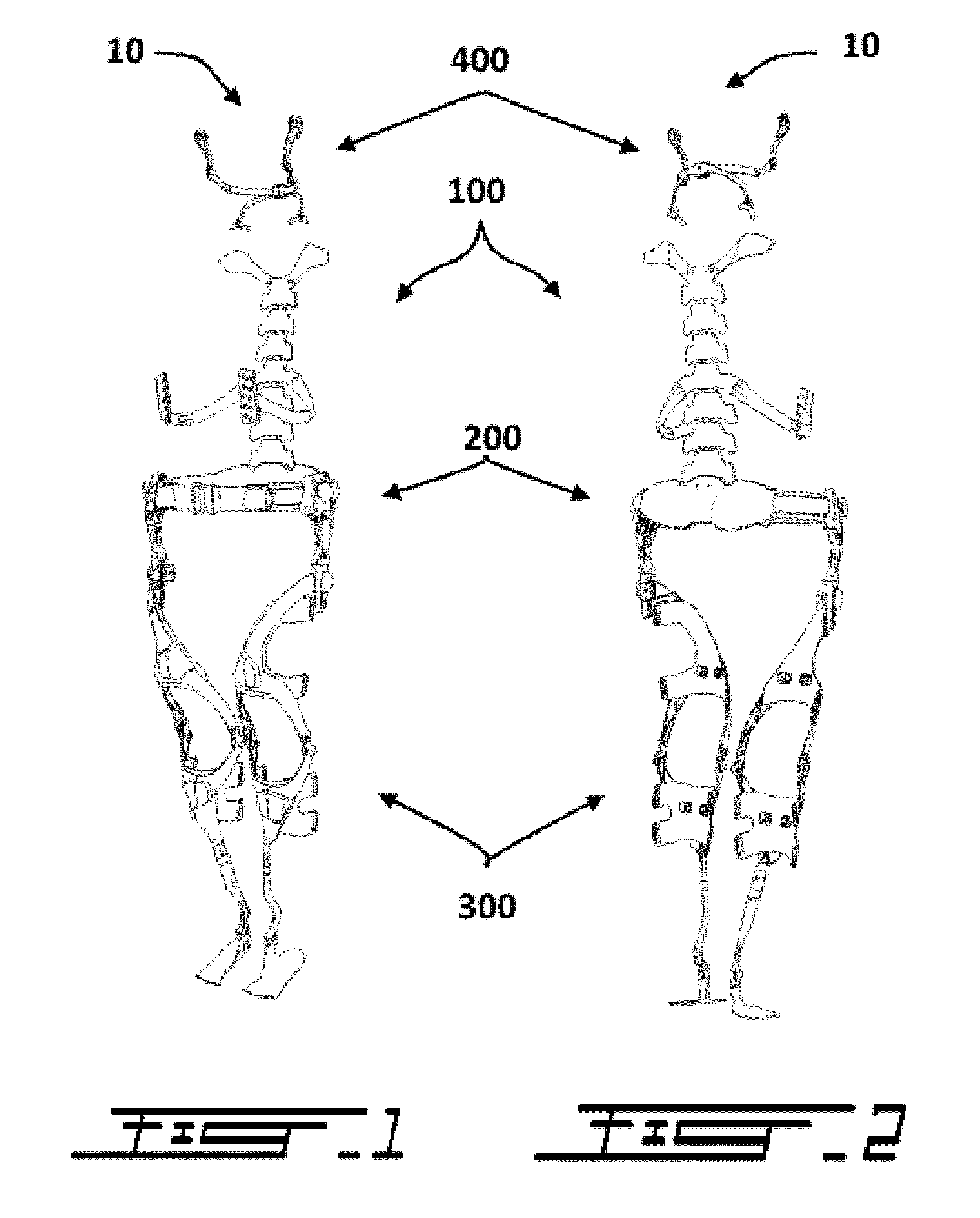
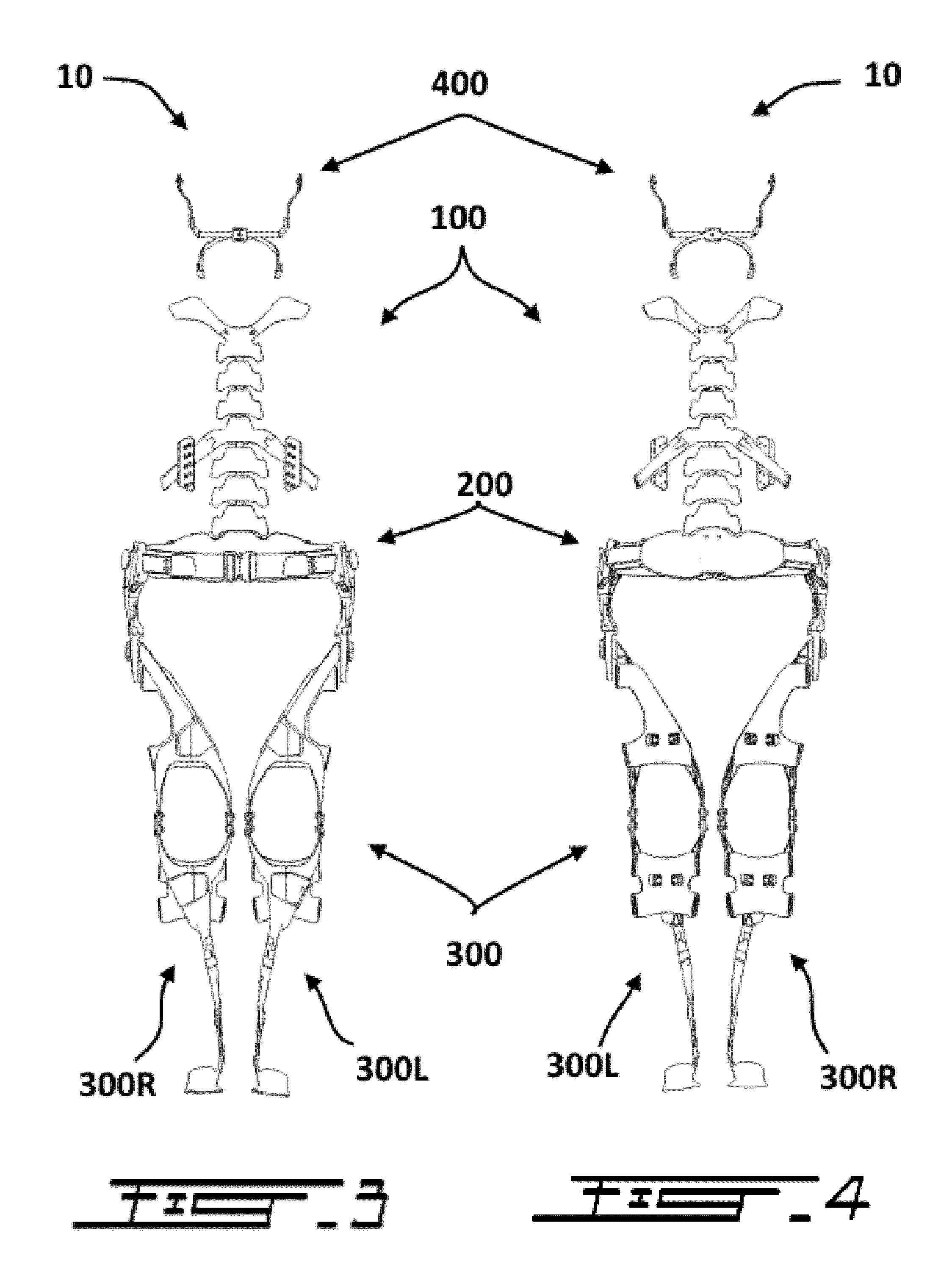
[0052]An exoskeleton in accordance with the principles of the present invention generally comprises at least three interconnected sections, 1) a torso section, 2) a hip section, and 3) leg sections. These three sections are interconnected such as to transfer the load normally carried by the torso, including the shoulders, chest, and back of the user, down to the ground via the hip section and then the leg sections.

[0053]To allow a load transfer which is more aligned with human biomechanics, the leg sections of the exoskeleton are generally connected to the sides of the hip section but are configured to transfer the load on the inner side of the feet.

[0054]In typical embodi...


PUM


Abstract

An exoskeleton designed to be worn by a user is generally configured to support and transfer the load supported by the head, the neck and / or the torso (shoulders, chest and / or back) of the user down to the ground. The exoskeleton is generally passive and comprises at least three interconnected sections: torso, hip, and leg sections. Each of the sections generally comprises of a plurality of interconnected rigid members which form the load-bearing structure of the exoskeleton. When a user wears the exoskeleton, load normally carried by the head, neck and / or torso of the user is at least partially supported and transferred to the ground by the exoskeleton, thereby reducing the load effectively supported by the user itself. The leg sections of the exoskeleton are designed to ensure that the load-bearing final location is located on the inner side of the feet, in accordance with human biomechanics.

Description

CROSS-REFERENCE TO RELATED APPLICATIONS[0001]The present patent application claims the benefits of priority of U.S. Patent Application No. 62 / 013,722, entitled “Passive Exoskeleton and Method of Using the Same”, and filed at the United States Patent and Trademark Office on Jun. 18, 2014, the content of which is incorporated herein by reference.FIELD OF THE INVENTION[0002]The present invention generally relates to exoskeletons and other wearable structures configured to assist humans in carrying loads, and more particularly relates to passive and / or non-powered exoskeletons and other passive and / or non-powered wearable structures configured to assist humans in carrying loads.BACKGROUND OF THE INVENTION[0003]Helping users carrying heavy loads has long been a need in many circumstances. For example, soldiers in the field, firefighters, police officers, antiriot squads, but also construction workers, and hikers, are often faced with the problem of carrying heavy loads, sometimes over lo...

Claims


Application Information

Patent Timeline
IPC IPC(8): A61F5/01A61F5/02
CPCA61F5/028A61F5/0102A61F2005/0155B25J9/0006
Inventor BUJOLD, ALAINSHEITOYAN, JEAN-MARCTREMBLAY, FRANCOISPAQUETTE, PATRICEPOHL, ALEKSANDERFORGET, SIMONOUANES, ANISVARY, ALAIN
Owner MAWASHI PROTECTIVE CLOTHING
Learn More