Composite lathe

a technology of composite lathes and lathes, which is applied in the direction of turning machine accessories, other manufacturing equipment/tools, manufacturing tools, etc., can solve the problems of limited machinability, lower supporting stiffness of the upper tool post, and adverse influence of machining accuracy

Inactive Publication Date: 2006-10-26
DMG MORI CO LTD
View PDF11 Cites 37 Cited by
  • Summary
  • Abstract
  • Description
  • Claims
  • Application Information

AI Technical Summary

Benefits of technology

[0009] The present invention was made in consideration of the above circumstances and it is an object thereof to provide a composite lathe allowing the overlapping of movement areas without lowering supporting stiffness of a tool post, and thus realizing improved machinability.
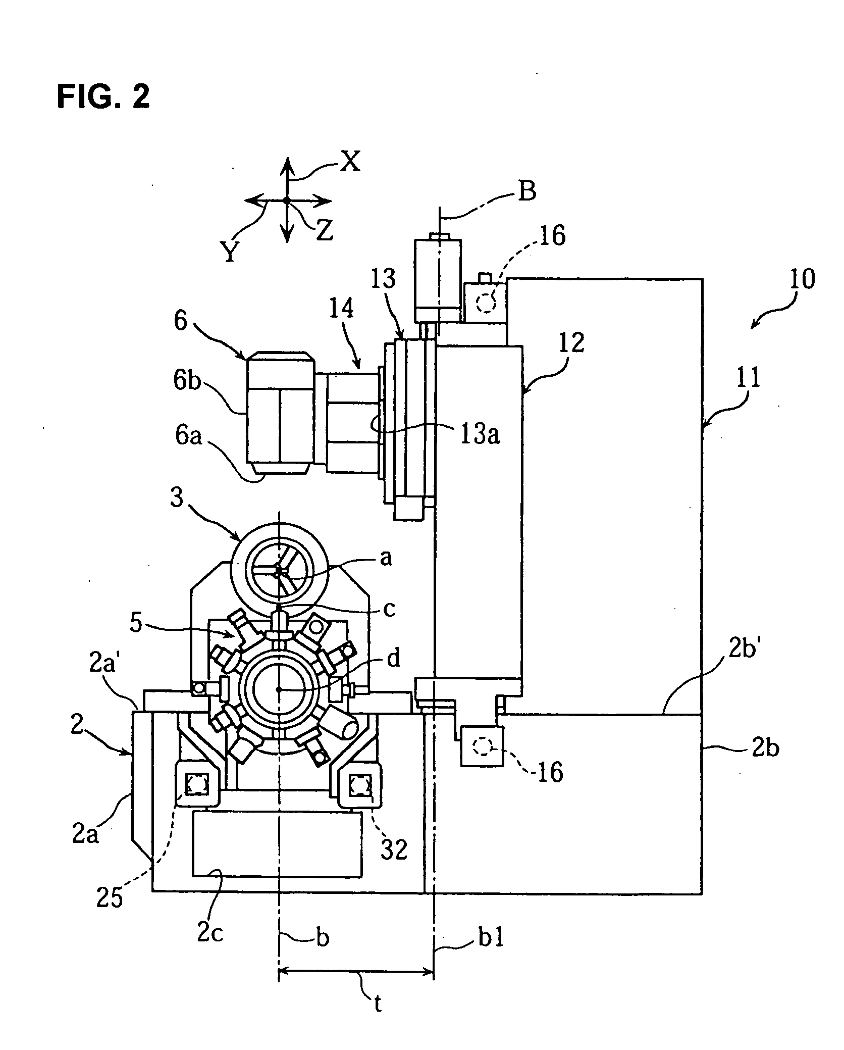
[0011] In the invention, the XY supporting plane by which the tool post is supported to be movable in the X-axis direction is set so as to intersect with the XZ supporting plane by which the third spindle is supported to be movable in the X-axis direction, and the axes of the movement in the X-axis direction of the tool post and the third spindle are set apart from the XZ supporting plane and the XY supporting plane. Therefore, it is possible to extend the movement area of the cutting point of the third spindle to the area under the cutting point of the tool post without any interference between the tool post and the third spindle, and the movement area of the cutting point of the tool post and the movement area of the cutting point of the third spindle can overlap each other, which can enhance machinability. In this case, since the tool post and the third spindle need not overhang, no deterioration in supporting stiffness thereof occurs.
[0015] In the above-described embodiment, the cutting point of the tool post is positioned vertically under the straight line connecting the axes of the first and second spindle headstocks, and the movement area of the third spindle is extended to the position under the cutting point of the tool post positioned at the rising end in the X-axis direction. Therefore, a tool blade edge position of the tool post and a tool blade edge position of the third spindle can be measured by one presetter. As a result, it is possible to measure the tool positions with a simple structure and at low cost.
[0017] In the above-described embodiment, since the tool spindle of the third spindle is supported to be rotary indexable around the Y axis, complicated machining by so-called B-axis driving is made possible.

Problems solved by technology

Incidentally, in the structure in which the upper tool post and the lower tool post are moved on the same plane as in the aforesaid conventional lathe, movement areas of cutting points of the upper and lower tool posts are limited, inhibiting each of them from moving into the movement area of the other, resulting in limited machinability.
However, such a structure tends to lower supporting stiffness of the upper tool post, giving an adverse influence to machining accuracy.

Method used


Image

  • Composite lathe
  • Composite lathe
  • Composite lathe

Examples


Embodiment Construction

[0036] An embodiment of the present invention will be hereinafter described based on the attached drawings.

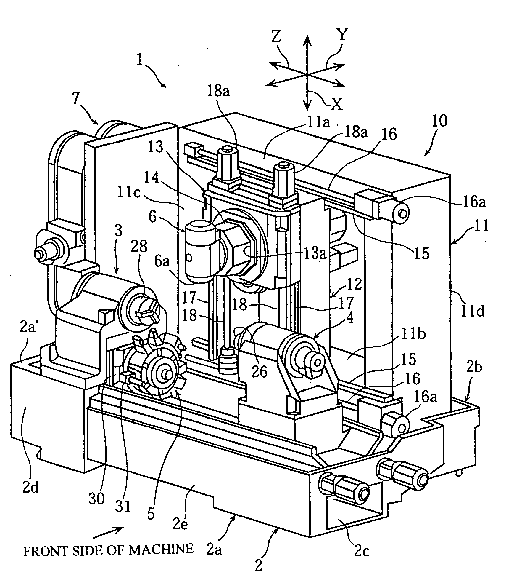
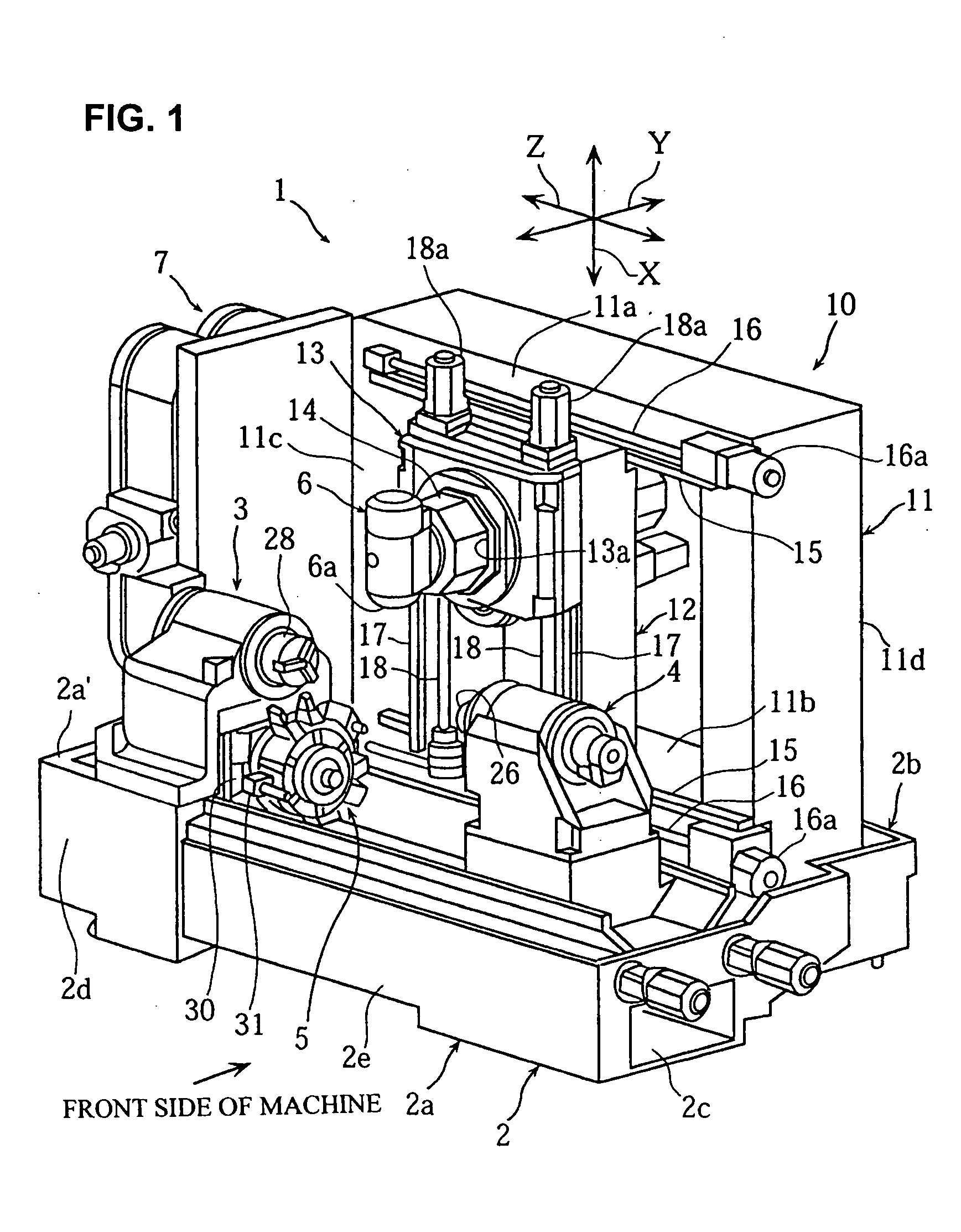
[0037]FIG. 1 to FIG. 18 are views to illustrate a composite lathe according to one embodiment of the present invention. FIG. 1 and FIG. 2 are a perspective view and a right side view of the composite lathe respectively, FIG. 3 and FIG. 4 are perspective views of a bed on which a first spindle headstock and a tool post are mounted, FIG. 5 is a front view of a supporting mechanism supporting a third spindle, FIG. 6 is a right side view of the first spindle headstock and the tool post, FIG. 7(a) to FIG. 7(c) are front views showing operations of the first spindle headstock, a second spindle headstock, and the tool post, FIG. 8 to FIGS. 11(a), (b) are views of the first spindle headstock, FIG. 12 is a perspective view of a cooling oil jacket of the first spindle headstock, FIG. 13 to FIG. 16 are views of the tool post, and FIG. 17 and FIG. 18 are views showing X-axis and Y-axis di...


PUM

PropertyMeasurementUnit
areaaaaaaaaaaa
supporting stiffnessaaaaaaaaaa
stiffnessaaaaaaaaaa

Abstract

To provide a composite lathe enabling the overlapping of movement areas without lowering supporting stiffness of a tool post, and thus realizing enhanced machinability. An XY supporting plane A by which a tool post 5 in is supported to be movable in an X-axis direction is set non-parallel to an XZ supporting plane B by which a third spindle 6 is supported to be movable in the X-axis direction, and an axis of the movement in the X-axis direction of the tool post 5 is set apart in a Y-axis direction from an axis of the movement in the X-axis direction of the third spindle 6.

Description

BACKGROUND OF THE INVENTION [0001] 1. Field of the Invention [0002] The present invention relates to a composite lathe including: a first and a second spindle headstock disposed on a bed; a tool post disposed between the first and second spindle headstocks to be movable in an X-axis direction; and a third spindle disposed on the bed to be movable in the X-axis direction, a Y-axis direction, and a Z-axis direction. [0003] 2. Description of the Related Art [0004] An example of a composite lathe of this type is structured such that a spindle headstock is disposed on a bed, and a lower tool post and an upper tool post are disposed on an outer lower side and an inner upper side of a vertical line going through an axis of the spindle headstock respectively to be movable in an X-axis direction and a Z-axis direction. [0005] This composite lathe adopts a structure such that an X-axis guide by which the upper tool post is supported to be movable in the X-axis direction and an X-axis guide by...

Claims


Application Information

Patent Timeline
Patent Type & Authority Applications(United States)
IPC IPC(8): B23P23/00
CPCB23B3/065B23B3/168B23P23/02B23Q39/025Y10T82/2541Y10T409/305656Y10T82/2508Y10T29/5114Y10T82/25Y10T82/2524Y10T82/2566Y10T409/307728
Inventor SASAZAWA, YUKINAGAMATSUMOTO, KAZUHIKOTOKUMA, TSUTOMU
Owner DMG MORI CO LTD
Why Eureka
Try Eureka