Contact device and electromagnetic switch using contact device

a contact device and electromagnetic switch technology, applied in the direction of electromagnetic relay details, high-tension/heavy-dress switches, electrical apparatus, etc., to achieve the effect of simple structure, simple structure, and reliable extinguishing

Inactive Publication Date: 2014-02-18
FUJI ELECTRIC FA COMPONENTS & SYST CO LTD
View PDF18 Cites 28 Cited by
  • Summary
  • Abstract
  • Description
  • Claims
  • Application Information

AI Technical Summary

Benefits of technology

[0010]The present invention, therefore, was conceived in view of the unsolved problem of the prior art, and an object of the present invention is to provide a contact device capable of easily extinguishing an arc generated between a fixed contactor and a movable contactor without using a permanent magnet, the arc being generated when the contact device is in an open state, and an electromagnetic switch that uses this contact device.
[0023]Moreover, applying the contact device having the abovementioned effect to the electromagnetic switch can provide an electromagnetic switch such as an electromagnetic contactor or an electromagnetic relay, which is capable of extinguishing an arc using a simple structure, the arc being generated when the electromagnetic switch is in an open state.

Problems solved by technology

However, the prior art Publications described in Patent Documents 1 and 2 have an unsolved problem where a permanent magnet is required to favorably extinguish an arc that is generated during the open state.

Method used


Image

  • Contact device and electromagnetic switch using contact device
  • Contact device and electromagnetic switch using contact device
  • Contact device and electromagnetic switch using contact device

Examples


Embodiment Construction

[0027]An embodiment of the present invention is described hereinafter with reference to the diagrams.

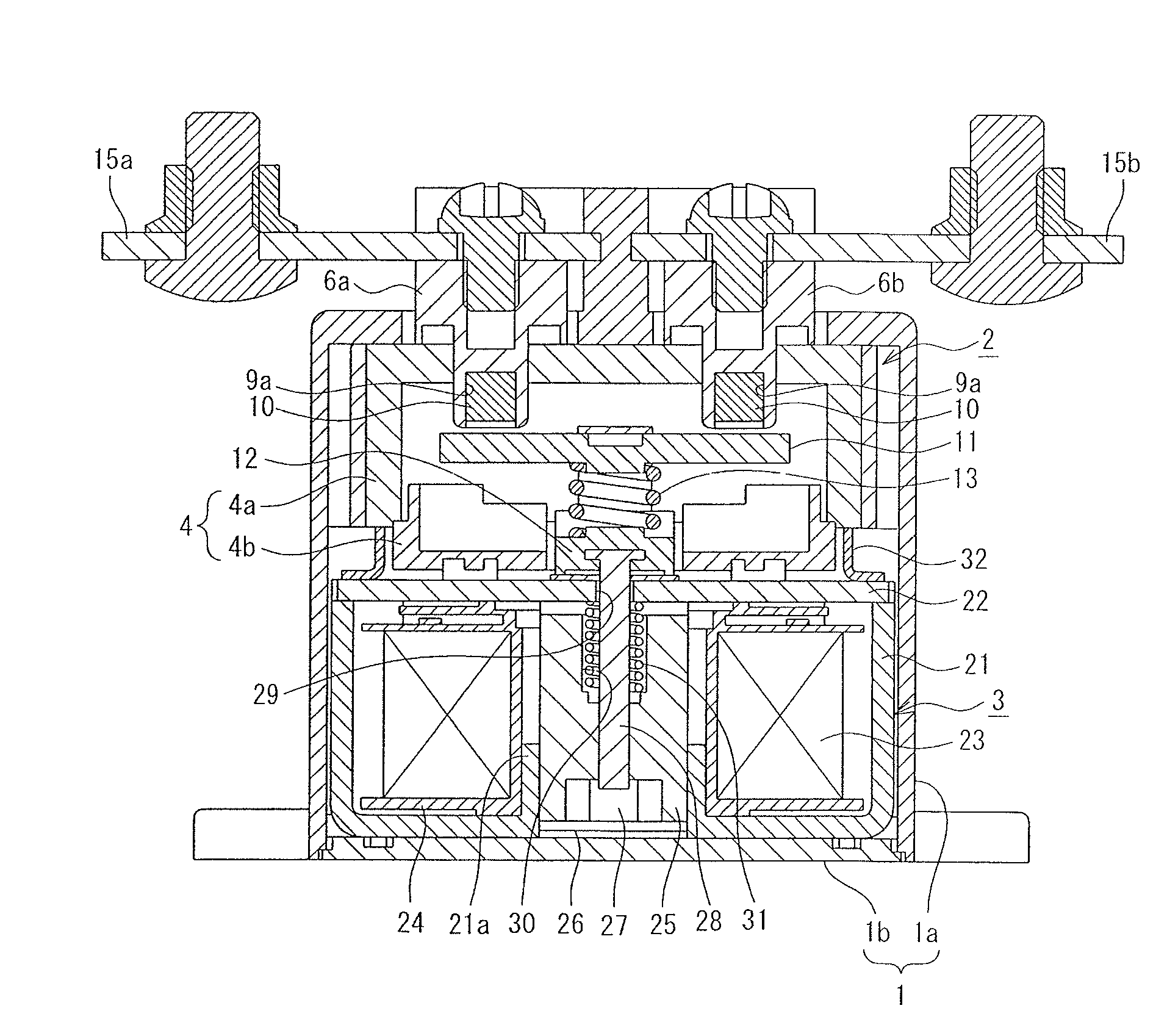
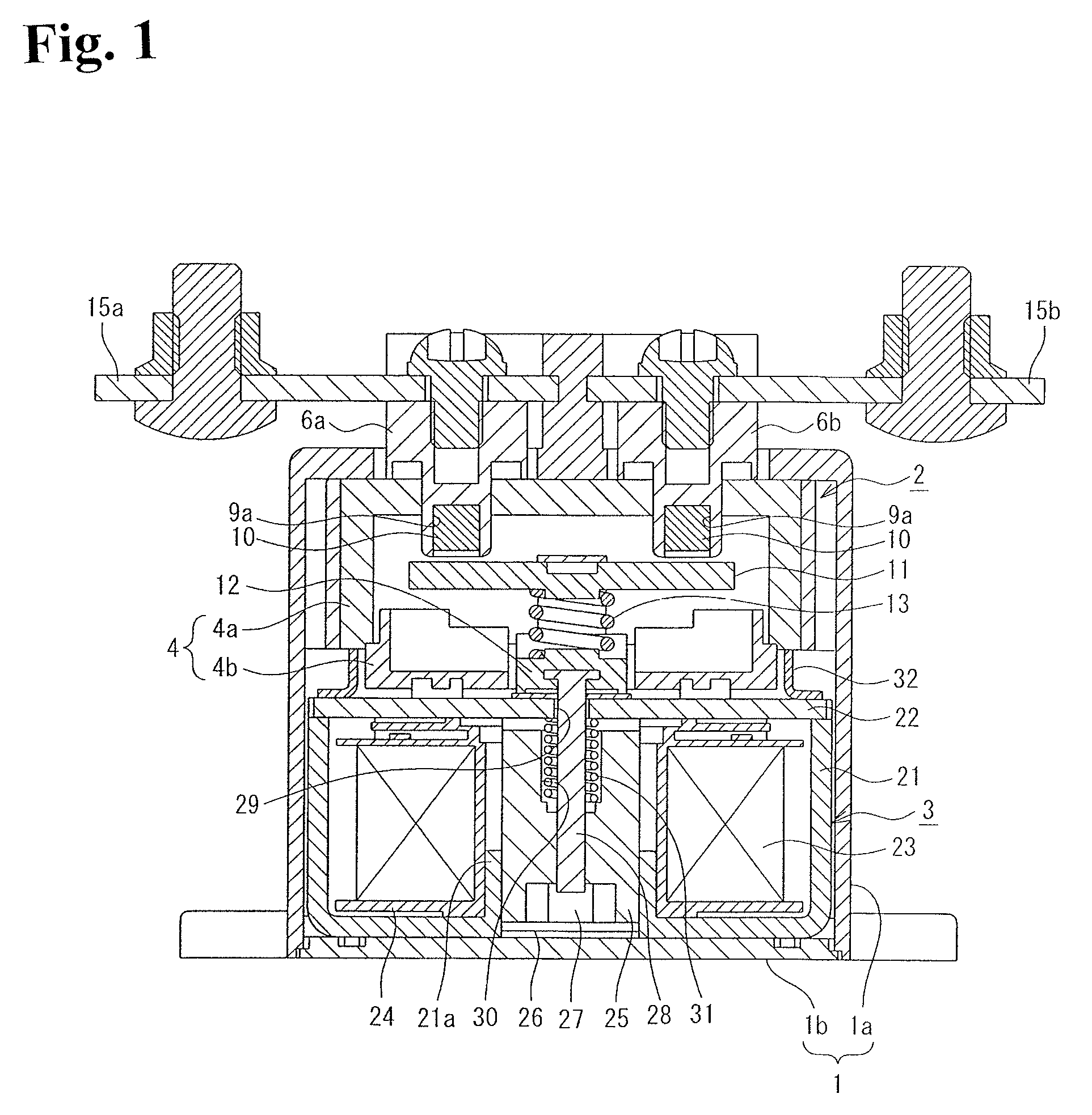
[0028]FIG. 1 is a cross-sectional diagram showing an example in which a contact device of the present invention is applied to an electromagnetic contactor functioning as an electromagnetic switch. In FIG. 1, reference numeral 1 represents an outer case made from, for example, a synthetic resin. This outer case 1 is configured by a tubular body 1a having an opened lower end surface, and a bottom plate 1b that closes the lower end surface of the tubular body 1a.

[0029]Within the outer case 1, a contact device 2 in which a contact mechanism is disposed, and an electromagnetic unit 3 serving as an electromagnetic device for driving the contact device 2 are stored in a manner that the electromagnetic unit 3 is positioned on the bottom plate 1b.

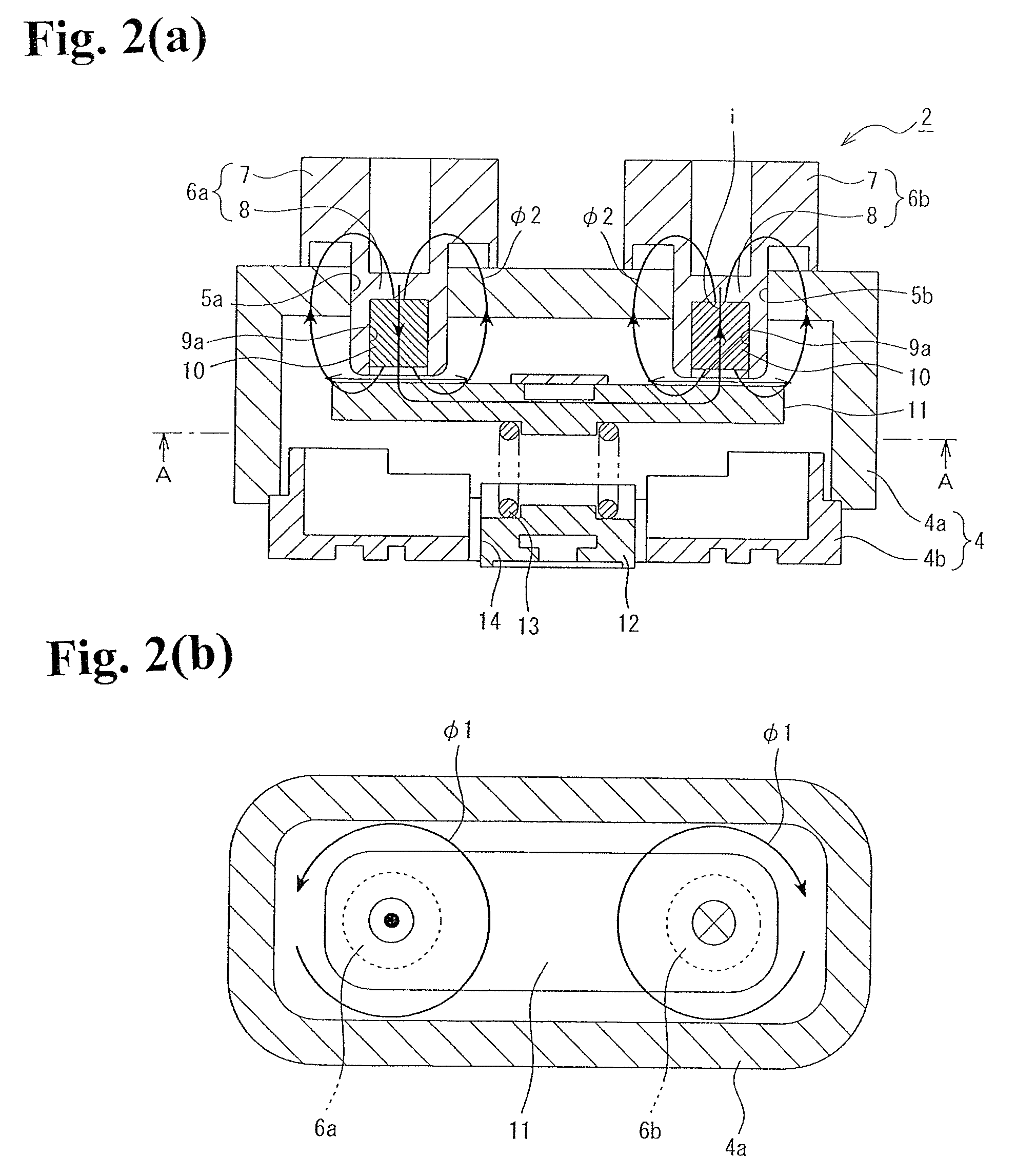
[0030]As is clear from FIGS. 2 and 3, the contact device 2 has an insulation airtight container 4 that has a dual structure of substantially cuboi...


PUM


Abstract

A contact device includes a pair of fixed contactors fixed to one side of an insulation container with a predetermined space therebetween and having a columnar shape with a tip end contact surface protruding at lease inside the insulation container, and a movable contactor disposed to be capable of contacting with and separating from the pair of fixed contactors. Surfaces of the pair of fixed contactors facing the movable contactor are formed of annular peripheral walls having a concave part at a center thereof. An annular arc is formed between the annular peripheral wall and the movable contactor when the contact device is in an open state.

Description

RELATED APPLICATIONS[0001]The present application is National Phase of International Application No. PCT / JP2011 / 003379 filed Jun. 14, 2011, and claims priority from Japanese Application No. 2010-180242, filed Aug. 11, 2010.TECHNICAL FIELD[0002]The present invention relates to a contact device having a fixed contactor and a movable contactor interposed into a current path, and an electromagnetic switch that uses the contact device, the contact device being capable of easily extinguishing an arc that is generated when the fixed contactor and the movable contactor are opened, that is, when the current is interrupted.BACKGROUND ART[0003]Among conventional electromagnetic relays and electromagnetic contactors functioning as contact devices for opening / closing current paths, various contact mechanisms have been proposed for extinguishing an arc that is generated when movable contactors and fixed contactors are opened to be separated from each other, in order to bring a closed state of the...

Claims


Application Information

Patent Timeline
Patent Type & Authority Patents(United States)
IPC IPC(8): H01H9/30H01H67/02
CPCH01H50/546H01H9/443H01H33/60H01H50/54
Inventor TAKAYA, KOUETSUSUZUKI, KENJINAKA, YASUHIRO
Owner FUJI ELECTRIC FA COMPONENTS & SYST CO LTD
Why Eureka
Try Eureka