Relating to coin dispensing

a coin dispenser and coin hopper technology, applied in the field of coin dispensers, can solve the problems of large number of complex parts, large number of internal parts of the hopper, and high mechanical complexity of the hopper,

Active Publication Date: 2014-03-11
INNOVATIVE TECH LTD
View PDF8 Cites 3 Cited by
  • Summary
  • Abstract
  • Description
  • Claims
  • Application Information

AI Technical Summary

Benefits of technology

[0020]The mechanism according to the first aspect of the invention provides an effective and mechanically simple solution to the double coin problem. It can be applied to coins of any size or shape but is yet less mechanically complex than prior art solutions. Further, the mechanism according to the first aspect of the invention is very compact and may therefore be combined with a wide variety of hopper types.
[0021]To maximize the efficiency of the coin strapping members, the coin transport means may optionally be arranged to urge coins along the coin dispensing path whilst the coins are in contact with the first and second stripping members. For maximum effect, the coin transport means may, for example, urge the coins by actively pushing them at a position opposed to the leading face of the urged coins.
[0022]Advantageously, the coin transport means may further comprise a rotatable disk containing one or more coin-retaining apertures, the disk being provided adjacent a coin source for filling the or each aperture; and a deflecting member arranged to divert, in use, coins located in the or each aperture along the coin dispensing path. Such an arrangement may optionally further comprise a motor arranged to drive the rotatable disk. Further, the transport means may preferably comprise urging means on the rotatable disk, the urging means being arranged to cooperate with the deflecting member to urge a coin located in a coin-retaining aperture along the coin dispensing path by rotation of the disk. The urging means and the deflecting member may, for example, comprise complementary meshed formations enabling continuous relative rotational movement between the urging means and the deflecting member.
[0024]To prevent a coin jam, the deflecting member may be spring biased and movable into a retracted position. The deflecting member may, for example, be pivotable about an elongate pin between a deflecting position and the retracted position. Such an arrangement represents a particularly effective and efficient solution to the problem of coin jams.
[0037]The ability to accrue a collection of different coins which have a value equal to a predetermined pay out total is possible due to use of the improved dispensing mechanism which ensures that only one coin, irrespective of its diameter or thickness, is dispensed at a time from the hopper.

Problems solved by technology

Although universal hoppers have great advantages, particularly since identifying and sorting extracted coins is an area of technology that is well evolved, they also have inherent difficulties associated with them.
One of the biggest challenges that must be overcome is the specific requirement for coins to be dispensed individually which arises, for example, because most coin sorting and identifying mechanisms, i.e. the mechanisms generally located immediately downstream of a universal hopper, only work reliably when supplied with a stream of individual (single) coins.
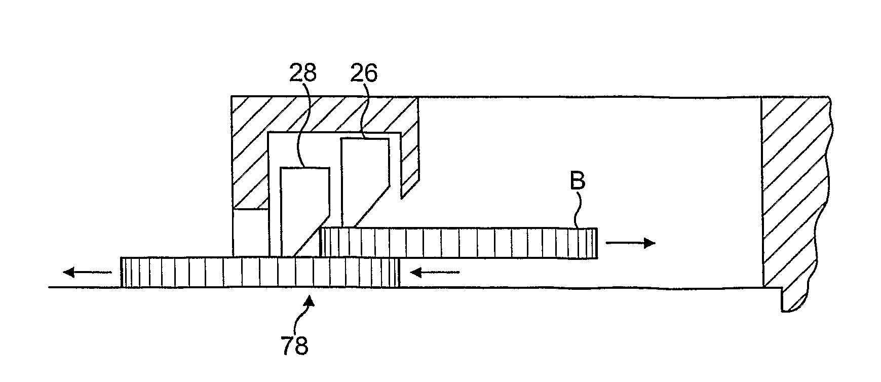
A key problem that is well documented in the prior art is that where a hopper's internal coin extraction mechanism is set up to extract coins of a comparatively greater thickness it is possible for two coins of a comparatively lower thickness to stack on top of each other to be dispensed in combination (i.e. not individually, as required) because they mimic the shape of a single thicker coin.
However, it has been found that the double coin problem generally forces a compromise having to be struck between (i) the variety of coins that can be processed in a given hopper and (ii) the mechanical complexity, and hence associated cost and reliability, of the internal parts of the hopper.
Universal hoppers that support a great variety of coin diameters, thicknesses and shapes generally require a large number of complex parts, particularly to deal with the double coin problem, and are thus expensive, whilst hoppers that have a simple, reliable and cost effective structure are generally limited to either a single dimension of coins or a very narrow range of coin sizes and shapes.
Clearly, EP 0017610 only offers a very limited solution to the double coin problem.
Additionally, the solution of EP 0017610 is only applicable where thinner coins indeed have a smaller diameter than thicker coins, which is not given in many monetary systems around the world.
It is clear that, although EP 0017610 does support a limited amount of variation in coin dimensions, it does not completely fulfil needs in this respect.
Nevertheless, what little flexibility EP 0017610 offers in terms of coin dimensions comes at a heavy price in the context of complexity of design.
The device of EP 0017610 comprises a large number of small components and the structure of the second stripping arm in particular is complicated and sensitive.
This in turn means that the device of EP 0017610 is expensive to manufacture and maintain and likely to be relatively vulnerable to faults and wear and tear.
Nevertheless, it requires painstaking calibration of the first and second stripping arms to take into account the specific dimensions of the range of coins that is processed.
There is also potential for coins to get wedged under the non-biased first stripping arm.
Further, the row of balls acting as the second stripping arm in particular is expensive to manufacture and replace (as would be necessary if the diameter of processed coins were to vary).
In summary, whilst DE 333 0441 supports a greater variation in coin dimensions, it is possibly even harder to maintain, configure and manufacture, largely as a result of the row of balls.
Additionally, the second stripping system, although flexible in terms of the dimensions of input coins is mechanically complex since it requires a drive mechanism and belt.
This mechanical complexity, coupled with the need for precise calibration makes the device of U.S. Pat. No. 4,657,035 particularly susceptible to faults and expensive to maintain and produce.
The complexity of the device of U.S. Pat. No. 4,657,035 is increased further by the fact that the relatively simple structure of the narrow stripping arm itself leads to the need for an additional closing element that stops small diameter coins from being dispensed in the slip stream of larger coins.
In summary, the prior art does not disclose a truly satisfactory (i.e. simple, effective and reliable) solution to the double coin problem.
Prior art devices are all either inflexible in their intake of coins or highly complex, or both.
Furthermore, most prior art devices must be carefully configured to match the coins that they are to process, which in turn leads to high maintenance costs and greater fault vulnerability.
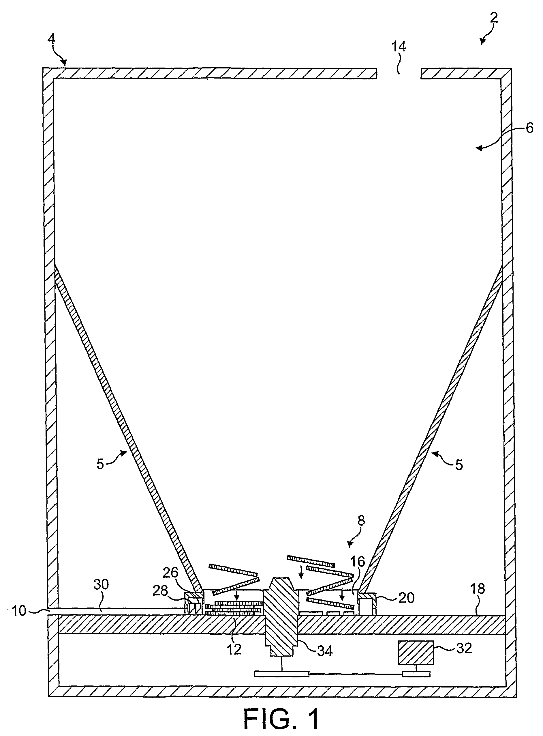
Finally it is noted that the vast majority of prior art solutions for the double coin problem are only suitable for use in planar coin disk type hoppers.
Thus hoppers that rely on a coin disk with apertures cannot at present be equipped with a system that would allow them to function effectively as universal hoppers, which are required to dispense a wide variety of coins individually.

Method used


Image

  • Relating to coin dispensing
  • Relating to coin dispensing
  • Relating to coin dispensing

Examples


Embodiment Construction

[0046]Referring firstly to FIG. 1, there is shown a coin dispensing hopper 2 comprising a housing 4, a coin store 6 for holding a bulk of coins, a coin dispensing mechanism 8 for separating and dispensing single coins from the bulk of coins, and a coin exit 10 from which the single coins are dispensed.

[0047]The coin store 6 is defined by the housing 4 and is essentially bowl shaped. It comprises a number of side walls 5 and a lower surface 12 towards which the bulk of coins held by the coin store 6 is drawn by gravity if the hopper 2 is positioned in its intended orientation. To allow the coin store 6 to be filled with a bulk of coins, the coin store 6 comprises a coin inlet 14 through which coins are provided.

[0048]The coin dispensing mechanism 8 is located on the lower surface 12 of the coin store 6 in order to be able to take in and process any coins that are provided in the coin store 6. Since the coins naturally fall to the bottom of the hopper 2, the coin dispensing mechanism ...


PUM


Abstract

A mechanism for separating single coins from a plurality of coins provided within a coin dispensing apparatus. The mechanism comprises a housing defining a coin dispensing path, coin transport means for urging coins along the coin dispensing path; and first and second biased coin stripping members located adjacent each other and disposed successively in the coin dispensing path at an outlet of the coin dispensing mechanism. The first and second stripping members together comprise a double outlet gate and each member is movable independently of the other by each urged coin to effect, in use, alignment and stripping of coins being dispensed.

Description

REFERENCE TO RELATED APPLICATIONS[0001]The present application is a national stage of International Patent Application PCT / GB2006 / 000249, filed 25 Jan. 2006, which claims the benefit of Great Britain Patent Application Serial No. 0501566.4, filed 25 Jan. 2005 and Great Britain Patent Application Serial No. 0502040.9, filed 1 Feb. 2005 all of which are hereby incorporated by reference.FIELD OF THE INVENTION[0002]The present invention concerns improvements relating to coin dispensing, and more particularly, though not exclusively, to a coin dispensing hopper incorporating an improved dispensing mechanism for dispensing coins. The term “coin” is used in its broadest sense throughout this specification and encompasses not only monetary coins but also tokens, medals and other similar discoid bodies.BACKGROUND OF THE INVENTION[0003]A key function of coin dispensing hoppers (which are simply referred to as hoppers hereafter) is to extract single coins from a bulk of coins they retain withi...

Claims


Application Information

Patent Timeline
Patent Type & Authority Patents(United States)
IPC IPC(8): G07D1/00
CPCG07D9/008
Inventor BELLIS, DAVID
Owner INNOVATIVE TECH LTD
Why Eureka
Try Eureka