
Electromagnetic Tow System For Nonpowered Ultralight Aircraft

Inactive Publication Date: 2016-04-07
BRYL GREGORY
View PDF11 Cites 2 Cited by
  • Summary
  • Abstract
  • Description
  • Claims
  • Application Information

AI Technical Summary

Benefits of technology

The patent describes an electromagnetic tow system that combines both braking and reeling functions in one compact mechanism. This system is simpler, light-weight, and manageable for small groups, making it more accessible for non-powered free flight. The system uses a single electric motor for both braking and driving force, which results in a smoother and friction-less tow. The system also utilizes the motor's electric braking properties for smooth payout and uses the same motor for both pay-in and pay-out modes. The invention also includes the use of aluminum side plates for heat sinking and the capture of converted mechanical energy to recharge the batteries. Overall, the invention provides a more efficient, compact, and manageable tow system for various applications.

Problems solved by technology

A friction brake must absorb lots of heat and, as the tow progresses, starts to have slipping problems due to high accumulated heat.
As a result, such systems, especially hydraulic ones, are bulky, expensive, cannot be handled easily by one or two people, and require significant maintenance.

Method used


Image

  • Electromagnetic Tow System For Nonpowered Ultralight Aircraft
  • Electromagnetic Tow System For Nonpowered Ultralight Aircraft
  • Electromagnetic Tow System For Nonpowered Ultralight Aircraft

Examples


Embodiment Construction

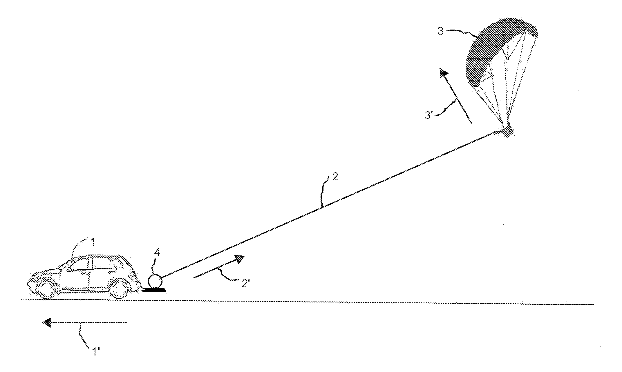
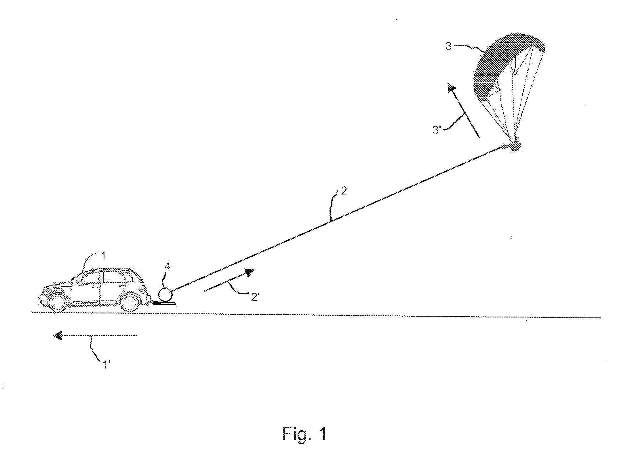
[0012]FIG. 1 illustrates a typical tow of a paraglider 3 using a payout method and employing a moving tow vehicle 1 on which the tow system 4 is mounted, with the tow line 2 being paid out during a tow. Arrow 1′ indicates the direction of the tow vehicle's motion. Arrow 2′ indicates the direction in which the tow line is paid out from the tow system 4. Arrow 3′ indicates the direction of the flight of the towed paraglider 3 during the tow.

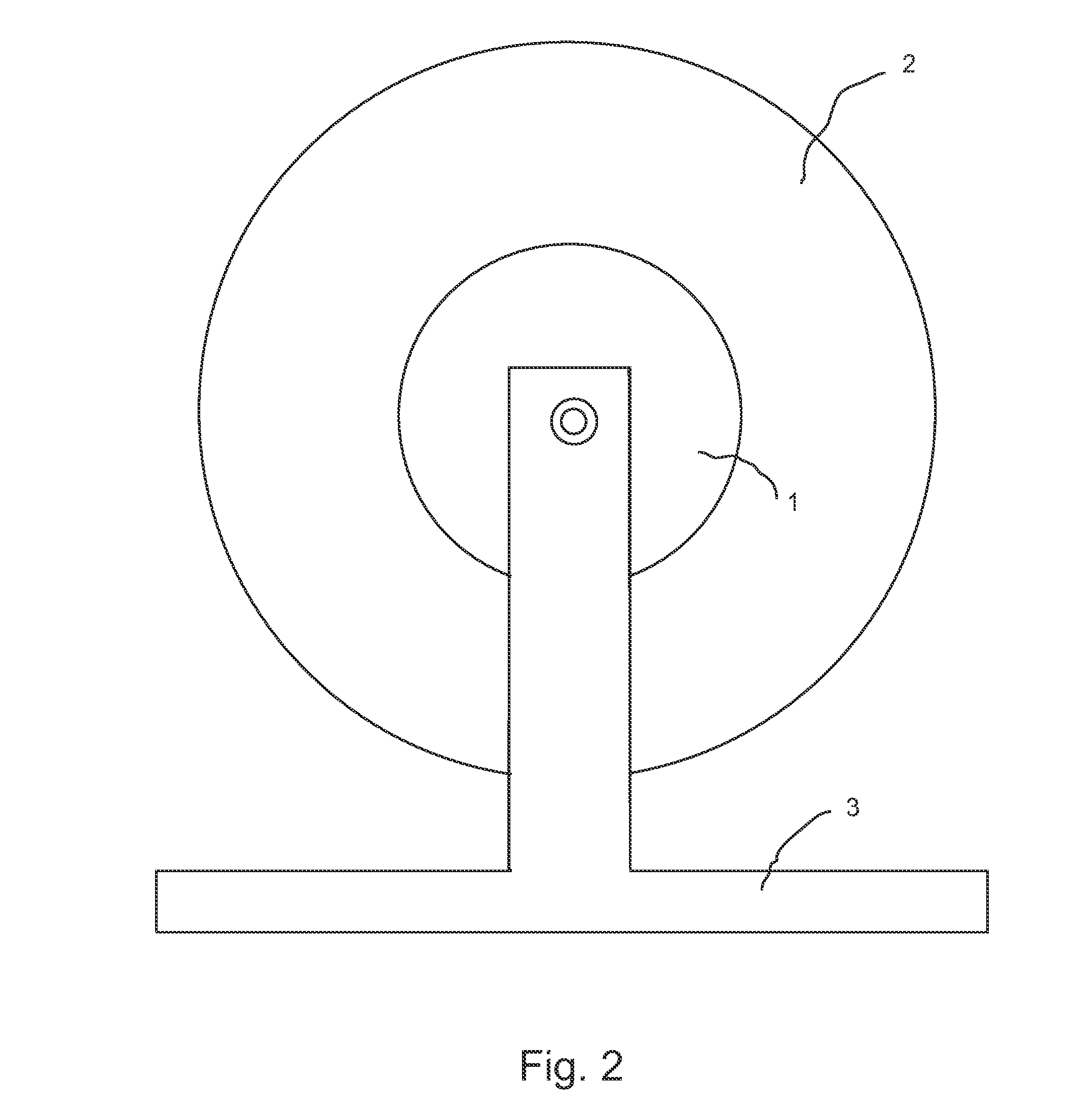
[0013]FIG. 2 and FIG. 3 illustrate a close-up of the electromagnetic tow system itself in its preferred configuration. A DC permanent magnet hub motor 1 is mounted on a frame 3 and is connected to a power supply (not shown). The round aluminum side plates 2 comprising the winch drum are mounted directly onto the sides of the hub motor 1 to form the winch drum. The drum holds the tow line (not shown), and its side plates 2 double up as heat sinks for the hub motor 1.

[0014]FIG. 4 illustrates the electrical circuit that facilitates the operation of th...


PUM


Abstract

An electromagnetic tow system for towing nonpowered ultralight aircraft that allows for towing under constant and controlled tow line tension using both pay-in and pay-out tow methods. An electric motor is mechanically connected to a winch holding the tow line and electrically connected to a power supply. When the line is paid out on tow, the motor is disconnected from its power supply and its non-field windings are shorted outright or connected through a resistor. As the motor's rotor rotates inside the motor's magnetic field (created by the motor's permanent magnets or powered stator windings) under the mechanical load of the towed aircraft, current is generated in the non-field windings of the motor, which creates braking torque opposing the mechanical rotation of the rotor and provides tow line tension. In a preferred configuration, a hub motor is used, with the winch drum side plates mounted directly onto the sides of the hub motor to serve as heat sinks cooling the motor; variable resistor is used to control the braking torque, plugging is available to increase braking torque when necessary, and the electromagnetic-braking-generated voltage and current are used to recharge the motor's portable power supply. The same motor is also used to rewind the tow line onto the spool as needed.

Description

BACKGROUND OF INVENTION[0001]The instant invention relates to the field of aviation. In geographical areas without mountains, often known as flat lands, nonpowered ultralight aircraft (such as paragliders and hang gliders) must be launched into flight by towing aloft. During such towing, the aircraft is connected to several thousand feet of tow line held by a winch drum. By pulling on the line, the aircraft is towed aloft to target altitude, whereby the line is released by the pilot to commence free flight.[0002]The two primary methods used for towing nonpowered ultralight aircraft aloft are known as a “pay-in” method and a “pay-out” method. Under the pay-in method, several thousand feet of tow line is first stretched out on the ground, with one end connected to the pilot and the other to the winch. The winch then pays the tow line in spooling it onto the drum (hence the name, pay-in), thus pulling the aircraft and towing it aloft. By contrast, under the pay-out method, the pilot is...

Claims


Application Information

Patent Timeline
IPC IPC(8): B64F1/08
CPCB64F1/08
Inventor BRYL, GREGORY
Owner BRYL GREGORY
Learn More