Prismatic battery with maximized and balanced current transmission between electrodes and terminals

a technology of current transmission and battery, which is applied in the direction of wound/folded electrode electrodes, sustainable manufacturing/processing, cell components, etc., can solve the problems of overheating, battery damage, and rechargeable batteries that are too fast to overwhelm the internal connection of the terminal to the electrode, and achieve maximum current transfer

Inactive Publication Date: 2002-06-27
NG ANDREW SUNG ON +1
View PDF4 Cites 11 Cited by
  • Summary
  • Abstract
  • Description
  • Claims
  • Application Information

AI Technical Summary

Benefits of technology

0030] It is another object of this invention to provide a prismatic battery

Problems solved by technology

Other batteries are formed of rectangular or cube shapes for inclusion in phones and electronic devices requiring batteries but lacking the space required for cylindrical designs or for large batteries for devices requiring large amounts of electrical current such as vehicles.
Rechargeable batteries, however, present another problem that must be considered due to the requirement that electrical current flow out of the battery at sufficient levels to power the device to which it is attached.
But once discharged, the rechargeable battery also has the requirement that electrical current be able to flow back into the battery to the electrodes at sufficient levels to charge the battery but not too fast to overwhelm internal connections from the terminal to the electrodes, overheat, or damage the battery.
However, this could result in a reduced power performance of the battery as often there is a limit as to how thin electrodes can be made.
Further, the diameter of cylindr

Method used


Image

  • Prismatic battery with maximized and balanced current transmission between electrodes and terminals
  • Prismatic battery with maximized and balanced current transmission between electrodes and terminals
  • Prismatic battery with maximized and balanced current transmission between electrodes and terminals

Examples


Embodiment Construction

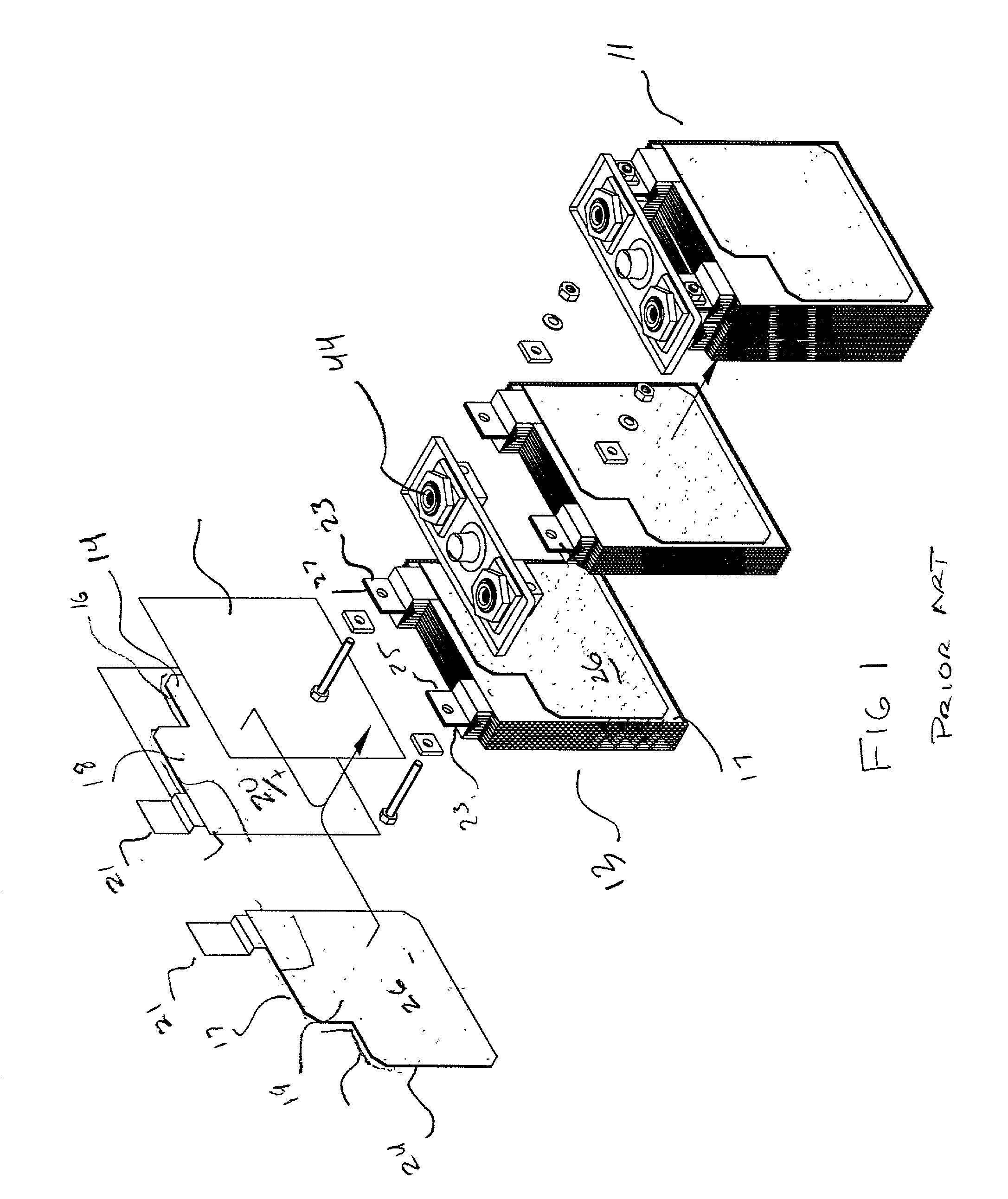
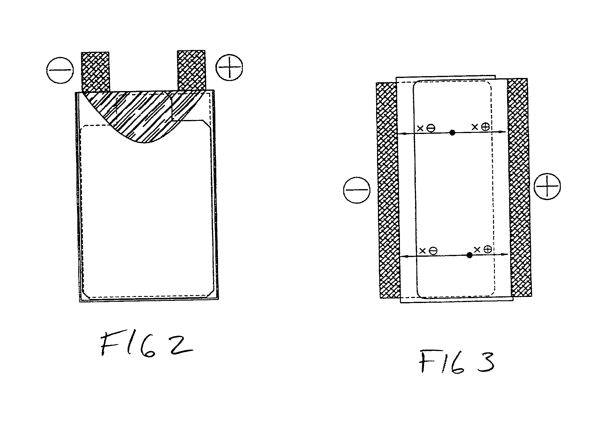
[0052] Referring now to FIGS. 1-2 which depict the prior art of conventionally manufactured prismatic cells. FIG. 1 depicts an exploded view showing a plurality of stacked electrodes 13 forming a conventionally configured prismatic battery cell 11. In conventional prismatic cells 11 positive electrodes 14 are formed by placement of positive active material 18 on a substrate 16 to form the positive active surface area 20.

[0053] Negative electrodes 24 are formed by the placement of negative active material 19 on substrate 17 thereby forming a negative active surface area 26. The positive electrodes 12 and negative electrodes 24 are placed in a stacked arrangement with separators 30 of non-conductive material sufficiently porous to allow passage of the chosen electrolyte therethrough, positioned in between each of the plurality of positive electrodes 14 and negative electrodes 24.

[0054] Transmission of the current or electrical from positive active surface area 20 and the negative acti...


PUM


Abstract

An improved battery cell having electrodes with active surface areas communicating along an entire edge with conductors thereby minimizing resistance and allowing for communication of electrical current to and from the battery at a high rate with an even discharge from the electrodes. Electrical current is produced by a plurality of electrodes formed of active material adhered to a conductive substrate. The plurality of electrodes is then stacked or wound to a desired configuration with a porous separator separating each adjacent electrode from the other. Communication along the entire edge of the formed electrodes on the conductive substrate with a conductive edge portion of the substrate, provide for maximum current flow in and out of the battery as well as well as reducing thermal concerns in high current applications. Elongated electrical conductors best made from copper are attached to the positive and negative edge portions communicating with substantially the entire active portions of the electrodes to provide a means of electrical current flow to and from the battery.

Description

[0001] This claims priority from provisional application Serial No. 60 / 257,352, filed Dec. 22, 2000. More particularly it relates to a rechargeable battery having electrical communication between the electrodes and the terminals communicating power to and from the exterior of the battery, which maximizes the flow of electrical current therebetween.background of the invention[0002] Conventional electrochemical devices such as batteries are manufactured to provide electrical power to a wide variety of devices needing a reliable portable supply of electricity. Such battery devices provide the electrical power for everything from watches to automobiles and as a consequence great value is placed on the energy density or electrical storage capacity of these devices and their continued ability to provide an adequate supply of electrical current to the communicating electrical device.[0003] For smaller batteries, the ease of manufacturing and the requirement of hermetic sealing in a pressur...

Claims


Application Information

Patent Timeline
IPC IPC(8): H01M6/10H01M10/04H01M50/529H01M50/533H01M50/534H01M50/54
CPCH01M2/0217H01M2/26H01M10/0431H01M10/0418H01M2/266Y02E60/10H01M50/103H01M50/54Y02P70/50H01M50/534H01M50/533
Inventor NG, ANDREW SUNG-ONLING, PETER
Owner NG ANDREW SUNG ON
Why Eureka
Try Eureka