Converter

a technology of converters and coils, applied in the field of converters, can solve the problems of reducing power throughput, adding complexity and cost to the design of ipt systems, and not fixed but varies in resonant frequency of transmitters, so as to achieve simple and cheaper manufacturing of receiver coils, output ripple, and the effect of reducing the cost of production

Inactive Publication Date: 2017-12-14
APPLE INC
View PDF2 Cites 10 Cited by
  • Summary
  • Abstract
  • Description
  • Claims
  • Application Information

AI Technical Summary

Benefits of technology

[0073]The circuit in FIG. 10 may be more useful than the circuit of FIG. 11 in situations where a fixed coupling coefficient between transmit and receive coils is present, or when circuit size and complexity is a priority over output voltage ripple, for example. This is because the circuit in FIG. 11 contains large DC inductors. These inductors provide stability for the system and act to smooth the DC output current such that the DC output ripple may be lower with this configuration but the circuit size is larger as compared with the FIG. 10 embodiment. Also a conventional single inductor receiver coil can be utilized so the manufacture of the receiver coil may be simpler and cheaper.

Problems solved by technology

All of these layers of control add complexity and cost to the design of IPT systems.
Another problem associated with IPT systems, is that for resonant systems, the resonant frequency of the transmitter is not fixed but varies according to the load on the receiver.
Thus, if the converter is supplying an output to the transmitter coil at a frequency that is no longer equivalent to the resonant frequency of the transmitter the power throughput is diminished and the system becomes less efficient.
A further problem associated with IPT systems is that the values of resonant components such as the transmitter or receiver coil and the resonant capacitors may vary due to manufacturing tolerances, age, temperature, power transmission distance changes and the presence of nearby metal or magnetic material, among other factors.
These variations affect the resonant frequency of the transmitter, which may fall out of resonance with the receiver causing power throughput to be diminished and the system to become less efficient.
A disadvantage of such a solution is that the frequency of the transmitted magnetic field will then vary over a range dependent on the resonant frequency of the transmitting coil.
This is problematic for two reasons: first, the receiver must adaptively retune to changes in the transmitted frequency or alternatively lose power; and secondly, it is undesirable to have the system operating over a range of frequencies since the available bandwidth might be too narrow.

Method used


Image

  • Converter
  • Converter
  • Converter

Examples


Embodiment Construction

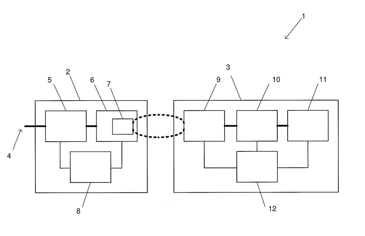
[0030]An inductive power transfer (IPT) system 1 is shown generally in FIG. 1. The IPT system includes an inductive power transmitter 2 and an inductive power receiver 3. The inductive power transmitter is connected to an appropriate power supply 4 (such as mains power). The inductive power transmitter may include an AC-DC converter 5 that is connected to an inverter 6. The inverter supplies a transmitting coil or coils 7 with an AC current so that the transmitting coil or coils generate an alternating magnetic field. In some configurations, the transmitting coils may also be considered to be separate from the inverter. The transmitting coil or coils may be connected to capacitors (not shown) either in parallel or series to create a resonant circuit.

[0031]FIG. 1 also shows a controller 8 within the inductive power transmitter 2. The controller may be connected to each part of the inductive power transmitter. The controller may be adapted to receive inputs from each part of the induc...


PUM


Abstract

An inductive power receiver 3 including at least two switches S1, S2 connected across a resonant circuit 802, the resonant circuit including an inductance and a capacitance, wherein a first switch S1 of the at least two switches is configured to switch into a first state based on a first event dependent on a receiver variable; and the first switch is configured to switch to a second state based on a second event independent of a receiver variable.

Description

FIELD OF THE INVENTION[0001]This invention relates generally to a converter particularly, but not exclusively, to a converter for an inductive power transfer system.BACKGROUND OF THE INVENTION[0002]Electrical converters are well known in the art and are available in many configurations for a variety of applications. Generally speaking, a converter converts an electrical supply of one type to an output of a different type. Such conversion can include DC-DC, AC-AC and DC-AC electrical conversions. In some configurations a converter may have any number of DC and AC ‘parts’, for example a DC-DC converter might incorporate an AC-AC transformer converter section.[0003]More specifically, ‘inverter’ is a term that can be used to describe a DC-AC converter. An inverter may exist in isolation or as part of a larger converter (as in the above example, which must invert the DC to AC prior to the AC-AC transformer). Therefore, ‘converter’ should be interpreted to encompass inverters themselves a...

Claims


Application Information

Patent Timeline
Patent Type & Authority Applications(United States)
IPC IPC(8): H02J50/12H02M3/335H02M7/217H02M7/219H02M7/5387
CPCH02J50/12H02M3/33592H02M2007/53878H02M2007/2195H02M7/217H02M3/33576H02M7/2195H02M7/53878Y02B70/10
Inventor REN, SAINING
Owner APPLE INC
Why Eureka
Try Eureka