
Wave-generating apparatus

Inactive Publication Date: 2010-01-28
INSTANT SPORT
View PDF8 Cites 29 Cited by
  • Summary
  • Abstract
  • Description
  • Claims
  • Application Information

AI Technical Summary

Benefits of technology

[0016]Although the profile may take any shape, in an especially advantageous solution the profile does not comprise any spaces or concavities intended to be directed towards the surfer when the wave-generating apparatus is operating (in other words, when the profile is moving), the aim being to enhance the safety of the surfer. Preferably, the profile is partially or totally hydrodynamic (having a low hydrodynamic resistance to advance coefficient) in order to reduce energy consumption and to minimize turbulence generation. In a specific embodiment the profile may present a fixed shape (e.g. a semi-rigid profile), regardless of whether it is moving or stationary. In another embodiment, the profile is inflatable, does not have a definite shape and is flexible so that during and due to its movement in relation to the floor, it takes on a hydrodynamic shape that is free of concavities directed towards the surfer. In this embodiment, a cylindrical inflatable profile is the easiest and cheapest solution to manufacture.
[0018]It is another object of this invention to provide a surfable wave-generating apparatus that is configurable. This means that the apparatus may be set up to generate waves of different types and sizes, in other words waves that are suitable for surfers of varying levels of experience. For example, the angle that the profile forms with the direction of displacement is preferably configurable so that the degree of difficulty of the wave may be changed (the smaller angle, the less difficult the wave).
[0019]The inventive apparatus presents a series of advantages over conventional wave-generating apparatus provided with a profile, either with a breaking point near the profile or with a breaking point distant from the profile.
[0020]In relation to apparatuses with a breaking point distant from the profile, the inventive apparatus, as with other apparatuses with a breaking point near the profile, does not require the floor of the aquatic environment to have a specific shape in order to determine when and how the wave breaks. Rather, the wave breaks with a shape that is controlled by the aforementioned profile parameters. Besides, the apparatus of the present invention advantageously requires less space to achieve a surfable wave, the wave already being surfable on top of the profile itself thanks to its elongated shape. Additionally, the apparatus of the present invention is more energy-efficient because of the preferred hydrodynamic shape of the profile.
[0021]Then, in relation to other known apparatuses that operate with a profile and with a breaking point near the profile, the inventive surfable wave-generating apparatus is able to guarantee maximum safety for the surfer while also generating waves of the same quality as natural waves. As has been explained, the use of a profile that is free of concavities and is preferably inflatable reduces risks. In contrast to surface-profile systems, the present invention lacks rigid or semi-rigid member (the profile or the base) or members that are provided with convexities, surfaces perpendicular to the movement or edges that may impact against the surfer located near the wave. Additionally, the apparatus of the present invention is feasible with a hydrodynamic profile in order to reduce energy consumption. Another advantage is that the wave generated by the apparatus can be surfed even at certain distance from the profile, which improves the security conditions for the surfer. The wave is surfable even at a certain distance thanks to the fact that the floor is near the profile, which favours that the wave maintains its slope and its optimum surfing shape as it gradually moves farther away from the profile.
[0022]In addition, the invention has an advantage over certain deep-profile systems in that the profile does not have to move inside a channel built for such a purpose. It is only required to move in relation to a floor, which may be positioned in a swimming pool, a lake, etc.

Problems solved by technology

One aspect shared by all these systems is that when they are used to generate waves for surfing they are not energy-efficient, the time intervals between waves are either too long or too short (if the natural frequency of the systems is used in order to reduce energy consumption), and, among other aspects, they also require a very large initial financial investment due to the fact that the swimming pool must have a shore-type floor, suitable for causing the wave to break and to dissipate the ripple effect.
For this reason, these systems are not energy-efficient when applied to the generation of waves suitable for surfing, as the other systems described previously.
Additionally, these systems may require a very high initial investment as, among other reasons, the swimming pool must be large enough and the floor of the swimming pool must be provided with a topography that allows the wave to break correctly and to dissipate the ripples.
As a result, these systems consume an acceptable amount of energy, thereby favouring their profitable use as a commercial surfing installation.
Besides, the shape and depth of the floor is not relevant.
These surfaces may seriously injure the surfer in the event that he falls or crashes against the profile.
Although these are very simple systems in conceptual terms, they are difficult to create in reality due to the difficulty in finding materials and mechanisms for building a flexible floor capable of withstanding the weight of a wave (it should be remembered that each metre of wave front with a depth of one metre weighs one ton) and of simultaneously deforming in order to acquire the shape of the wave, all without posing a danger to the user.
This system is deemed to present certain drawbacks: it is unable to generate waves with an escape effect as, due to the presence of the channel, the turbulent water of the part of the wave that has broken has nowhere to escape to and ends up filling the entire width of the channel; the walls of the channel make the ripples of the waves take too long to dissipate; the surfer may be thrown against the walls of the channel when falling off the wave.

Method used


Image

  • Wave-generating apparatus
  • Wave-generating apparatus
  • Wave-generating apparatus

Examples


Embodiment Construction

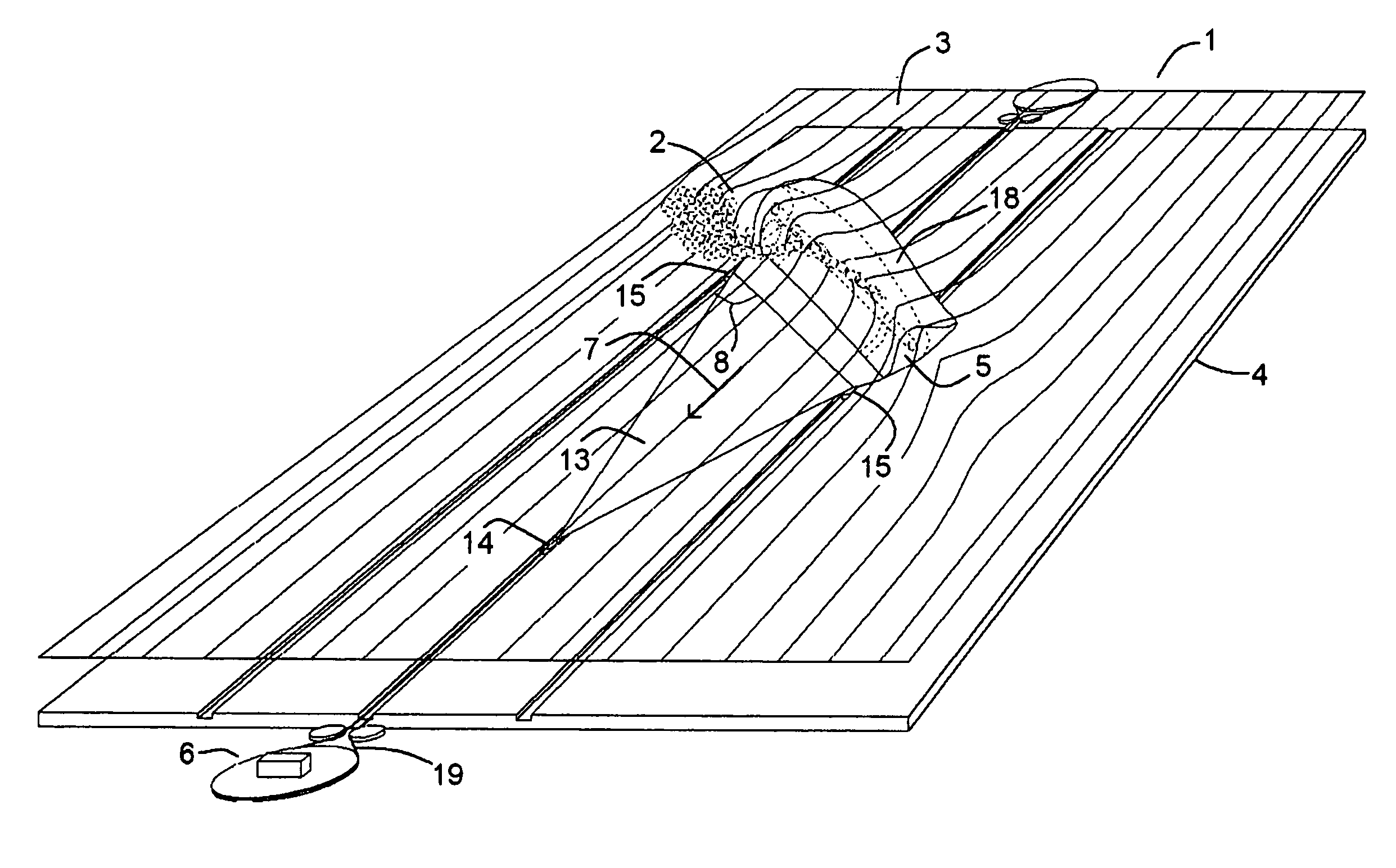
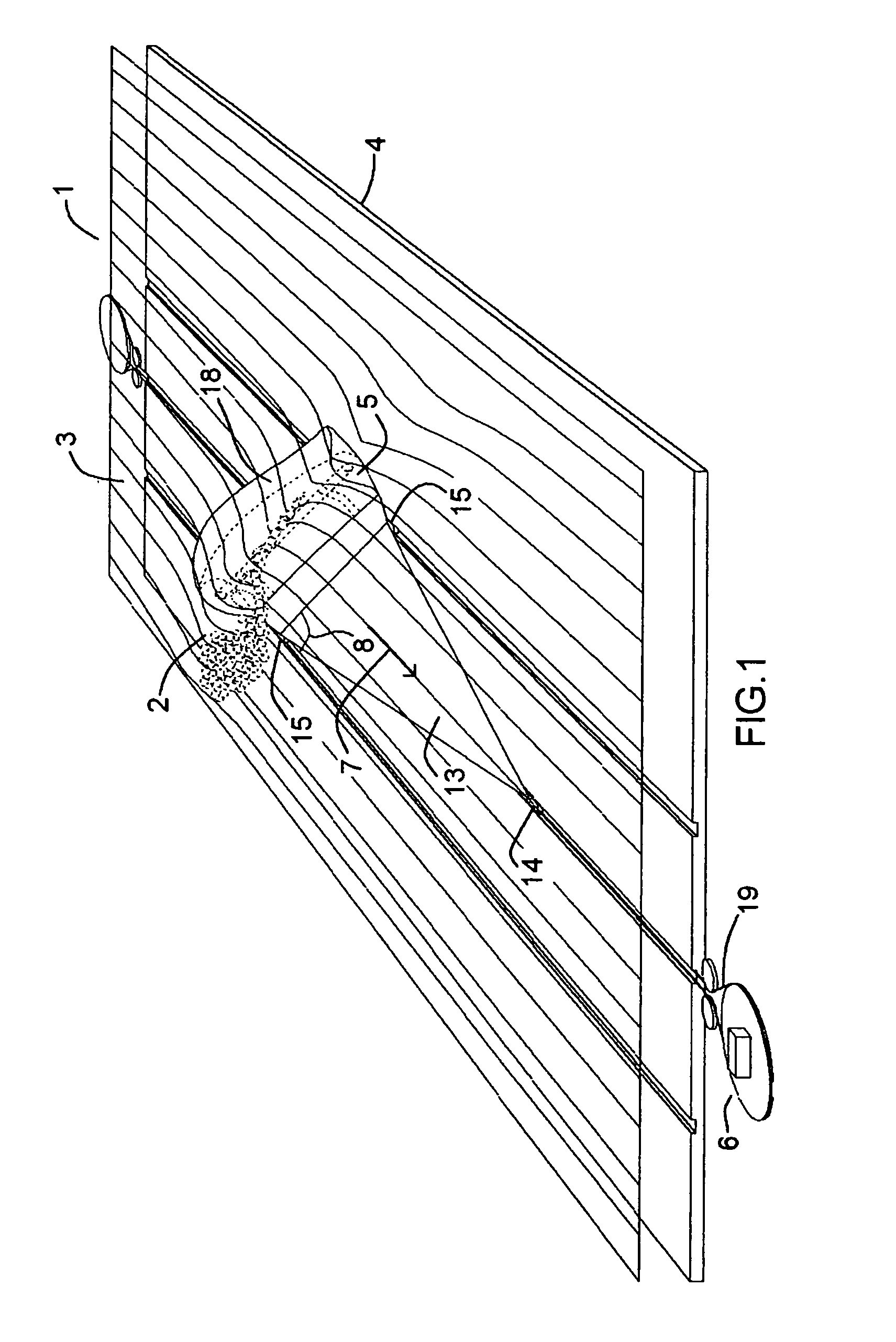
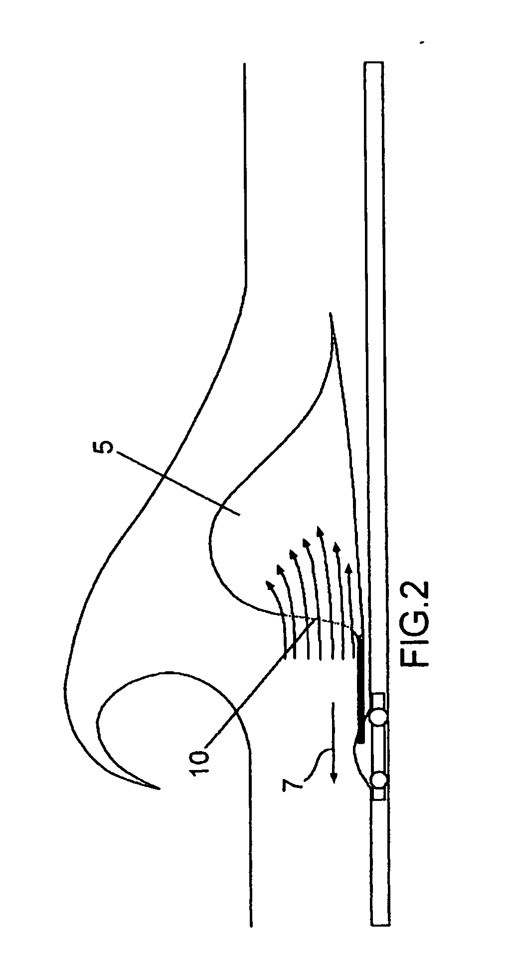
[0036]FIG. 1 shows an embodiment of an apparatus (1) for generating waves (2) in an aquatic environment (3). The apparatus (1) comprises a floor (4) that is substantially horizontal, i.e. that has a uniform depth in relation to the surface of the aquatic environment (3). The floor (4) is formed, for example, by an essentially flat sheet of concrete built on the bottom of a lake or swimming pool, by compacted earth on the bottom of a lake or swimming pool, or by sheets of metal inside a collapsible swimming pool. Situated on the floor (4), the apparatus (1) comprises a substantially elongated profile (5), which moves in relation to the floor (4) in a direction of displacement (7) thanks to the action of a drive mechanism (6). When the profile (5) moves, a surfable wave (2) is created on top of it.

[0037]As shown in the figure, the substantially elongated profile (5) forms an angle (8) other than 90° with the direction of displacement (7). As a result, the front of the wave (2) generat...


PUM


Abstract

Wave-generating apparatus (1) that is installed in an aquatic environment (3) and which comprises, as its main elements, at least one elongated profile (5) that moves tangentially in relation in relation to a uniformly-deep floor (4) by the action of a drive mechanism (6). As a result, a wave (2) forms on the profile (5) and moves along with the profile (2). The profile (5) is disposed to form an angle (8) other than 90° with the direction of displacement (7), the purpose being to generate a wave (2) with an escape area and which can therefore be surfed. Some parameters of the apparatus (1) may be adjusted for the purpose of changing the degree of difficulty of the wave (2) that is generated.

Description

TECHNICAL FIELD[0001]The invention relates to a wave-generating apparatus for generating waves suitable for surfing.PRIOR ART[0002]Waves generated artificially in an aquatic environment may only be considered suitable for surfing (i.e. they may be surfed using the same techniques and the same surfboards as used for natural waves) if they meet a series of requirements. Firstly, they must be relatively large in size (with a minimum height of 0.5 m and preferably taller than 1 m). Secondly, they must move in relation to a fixed point and said displacement must occur at a similar speed to the speed at which natural waves move at the coastline (where the wave current is between −2 and 2 m / s and the wave speed, which is proportional to the height of the wave, is approximately 6 m / s for a wave that is 1.5 m high). Thirdly, the waves generated must present the so-called “escape effect”, in other words, they must simultaneously present a breaking area and an area about to break, thereby allo...

Claims


Application Information

Patent Timeline
IPC IPC(8): A47K3/10
CPCA63B69/0093A63B69/0066E04H4/0006
Inventor ODRIOZOLA SAGASTUME, JOSE MANUEL
Owner INSTANT SPORT
Learn More