
Tunable laser

A technology for tuning lasers and tuning units, applied to lasers, laser components, semiconductor lasers, etc., to achieve reliable, high reliability, and easy manufacturing effects

Active Publication Date: 2007-03-28
NEC CORP
View PDF1 Cites 28 Cited by
  • Summary
  • Abstract
  • Description
  • Claims
  • Application Information

AI Technical Summary

Problems solved by technology

[0012] The purpose of the present invention is to provide a highly reliable, high-performance and inexpensive tunable laser, which overcomes the shortcomings of existing tunable lasers that have problems in practical applications

Method used


Image

  • Tunable laser
  • Tunable laser
  • Tunable laser

Examples


Embodiment Construction

[0036] Hereinafter, embodiments of the present invention will be described based on the drawings.

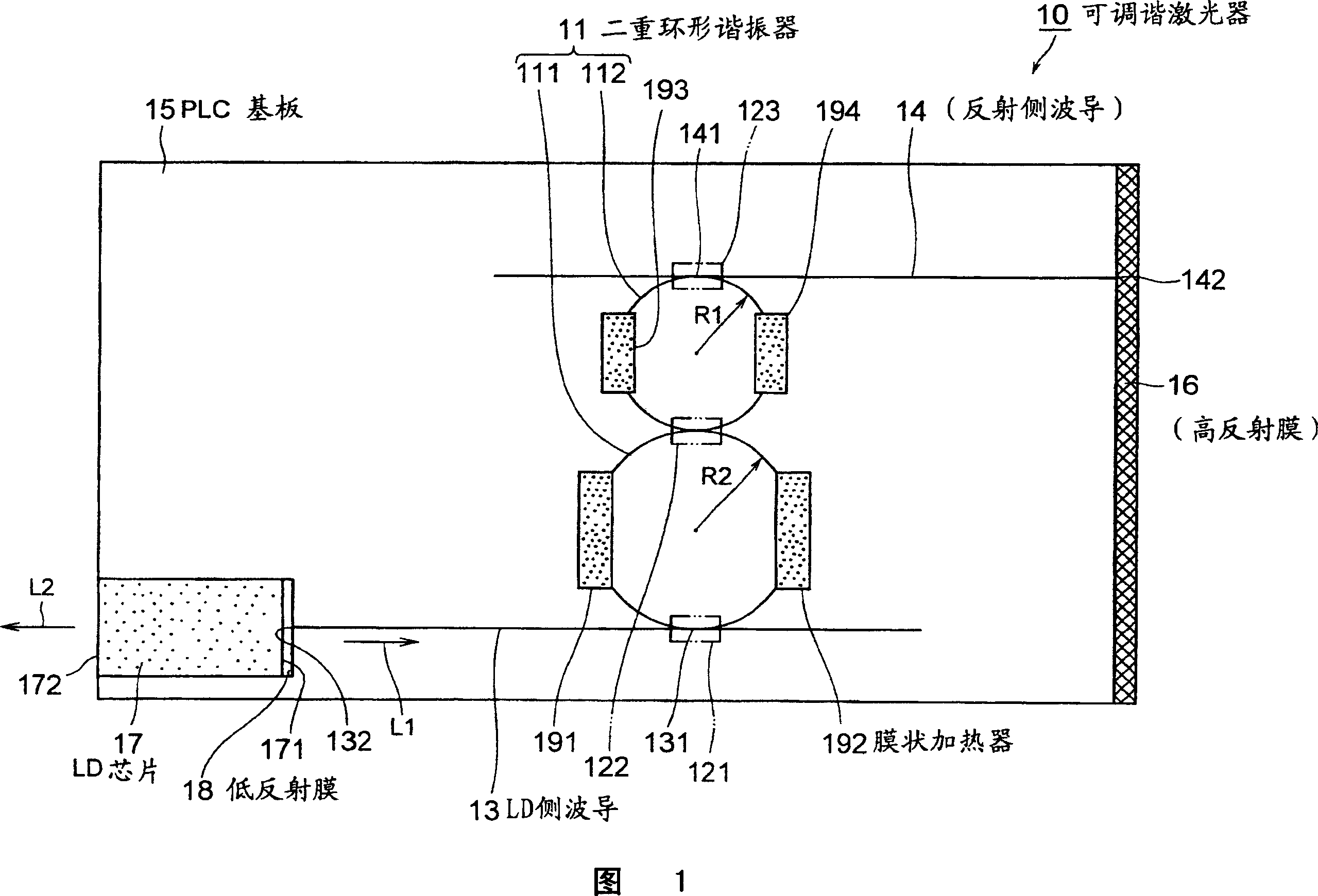
[0037] FIG. 1 is a plan view showing a first embodiment of a tunable laser according to the present invention. Hereinafter, it demonstrates based on this figure.

[0038] The tunable laser 10 of this embodiment includes: a double ring resonator 11, ring resonators 111 and 112 composed of ring waveguides with different optical paths from each other, connected through a directional coupler 122; LD side waveguide 13, through a directional A coupler 122, one end 131 is connected to the ring resonator 111; the reflection side waveguide 14 is connected to the ring resonator 112 through a directional coupler 123, and one end 141 is connected to the ring resonator 112; a PLC substrate 15 is formed with ring resonators 111, 112, LD The side waveguide 13 and the reflective side waveguide 14; the high reflection film 16 is arranged on the other end 142 of the reflective side waveguide 14;...


PUM


Abstract

The invention provides a tunable laser with high reliability and high performance, and of low cost. A tunable laser (10) comprises a double ring resonator (11) where ring resonators (111, 112) of different sizes are coupled through a directional coupler (122), an LD side waveguide (13) connected at one end (131) to the ring resonator (111) through a directional coupler (121), a reflection side waveguide (14) connected at one end (141) to the ring resonator (112) through a directional coupler (123), a PLC board (15) on which the ring resonator (111) and the like are formed, a high reflection film (16) provided at the other end (142) of the reflection side waveguide (14), an LD chip (17) having a low reflection film (18) formed on either of two opposite emission end faces (171, 172) and coupled optically with the other end (132) of the LD side waveguide (13), and film-like heaters (191-194) for varying the resonance wavelength of the double ring resonator (11).

Description

technical field [0001] The present invention relates to, for example, a tunable laser used in a WDM (Wavelength Division Multiplexing) transmission system and the like. Background technique [0002] Embracing the era of broadband, the introduction of a WDM transmission system that enables the correct and efficient use of optical fibers and enables communication of multiple optical wavelengths with one device is in progress. Recently, practical applications of DWDM devices (high-density wavelength division multiplexing devices) that multiplex tens of optical wavelengths to enable higher-speed transmission are also expanding. Along with this, light sources corresponding to each wavelength are required in each WDM transmission system, and the required number is rapidly increasing along with high multiplexing. Furthermore, recently, for commercial purposes, ROADM (Reconfigurable optical add / drop multiplexers) that perform Add / Drop of arbitrary wavelengths at each node is being ...

Claims


Application Information

Patent Timeline
Patent Type & Authority Applications(China)
IPC IPC(8): H01S5/14G02B6/12G02B6/34G02F1/01H01S5/00H01S5/02H01S5/0687H01S5/10
CPCH01S5/06804H01S5/02446G02B6/12007G02F2203/15H01S5/0687H01S5/0654G02B6/12004H01S5/02248G02F1/0147H01S5/142G02F1/011H01S5/02325H01S5/14
Inventor 山崎裕幸
Owner NEC CORP
Learn More