

Vehicle-mounted 360-degree panorama mosaic method
A picture and coordinate system technology, applied in image data processing, instrumentation, calculation, etc., can solve the problems of poor robustness, noise sensitivity, inability to achieve real-time and accuracy, and achieve high accuracy and reduce errors.
- Summary
- Abstract
- Description
- Claims
- Application Information
AI Technical Summary
Problems solved by technology
Method used
Image

Examples
Embodiment Construction
[0034] In order to enable those skilled in the art to better understand the technical solutions in the present invention, the technical solutions in the embodiments of the present invention will be clearly and completely described below in conjunction with the drawings in the embodiments of the present invention. Obviously, the described The embodiments are only some of the embodiments of the present invention, not all of them. Based on the embodiments of the present invention, all other embodiments obtained by persons of ordinary skill in the art without creative efforts shall fall within the protection scope of the present invention.
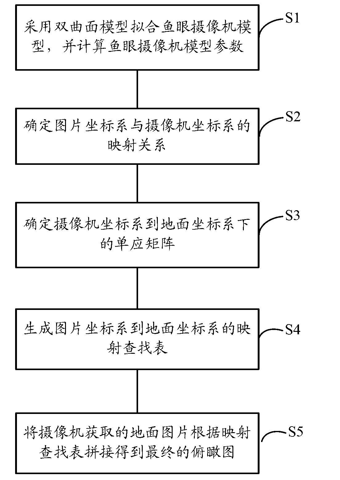
[0035] ginseng figure 1 As shown, the vehicle-mounted 360-degree panorama stitching method of the present invention comprises the following steps:
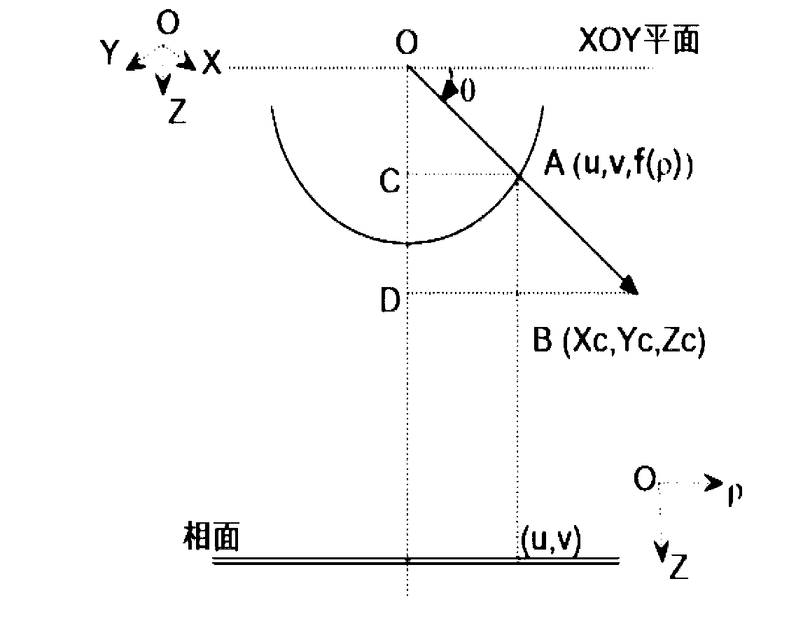
[0036] S1, using a hyperboloid model to fit the fisheye camera model, and calculating the parameters of the fisheye camera model;
[0037] S2. Determine the mapping relationship between the imag...
PUM
 Abstract
Description
Claims
Application Information