Non-contacting crack sensor

a crack sensor and non-contact technology, applied in the direction of instruments, structural/machine measurement, using mechanical means, etc., can solve the problems of difficult correlating results from acoustic detection methods, degrade material integrity, and high cost, and achieve low cost and reliable material integrity

Inactive Publication Date: 2005-10-13
XENOTRAN
View PDF8 Cites 48 Cited by
  • Summary
  • Abstract
  • Description
  • Claims
  • Application Information

AI Technical Summary

Benefits of technology

[0007] The object of this invention is to remotely detect cracks in materials. Another object of this invention is to provide a sensor which serves the dual purpose of antenna and crack sensing gauge. Still another object of the present invention is to provide a very low cost sensing device that provides reliable material integrity information.

Problems solved by technology

Disadvantages of using optical fibers are that they are expensive to incorporate into the composite structure, and may additionally degrade material integrity [2].
Composite materials are not isotropic, making correlating results from acoustic detection methods difficult.
The hybrid approach requires more components and has potentially lower reliability.
In either implementation, these systems have a number of deficiencies, including large size, reduced reliability, and high cost.

Method used


Image

  • Non-contacting crack sensor
  • Non-contacting crack sensor
  • Non-contacting crack sensor

Examples


Embodiment Construction

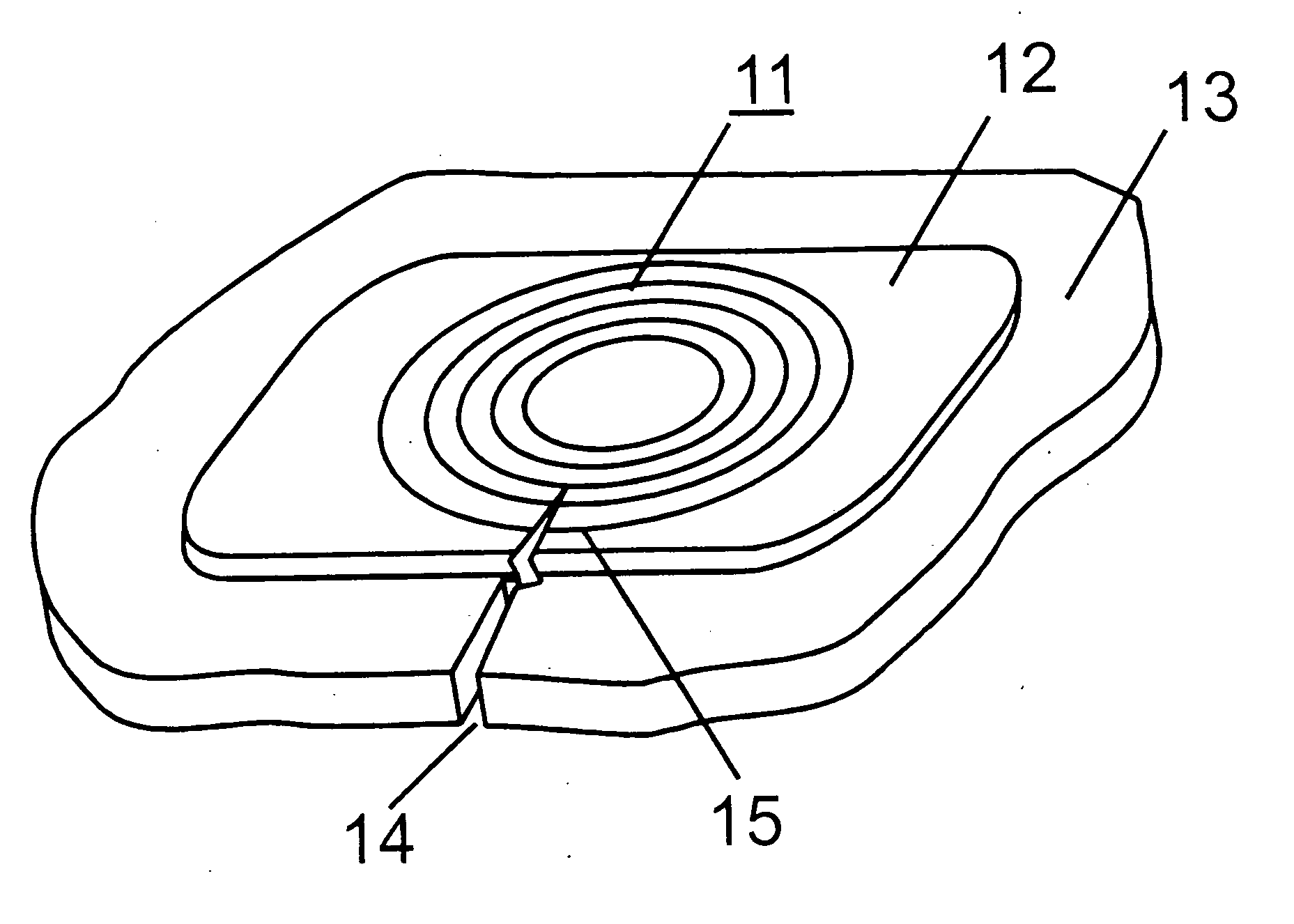
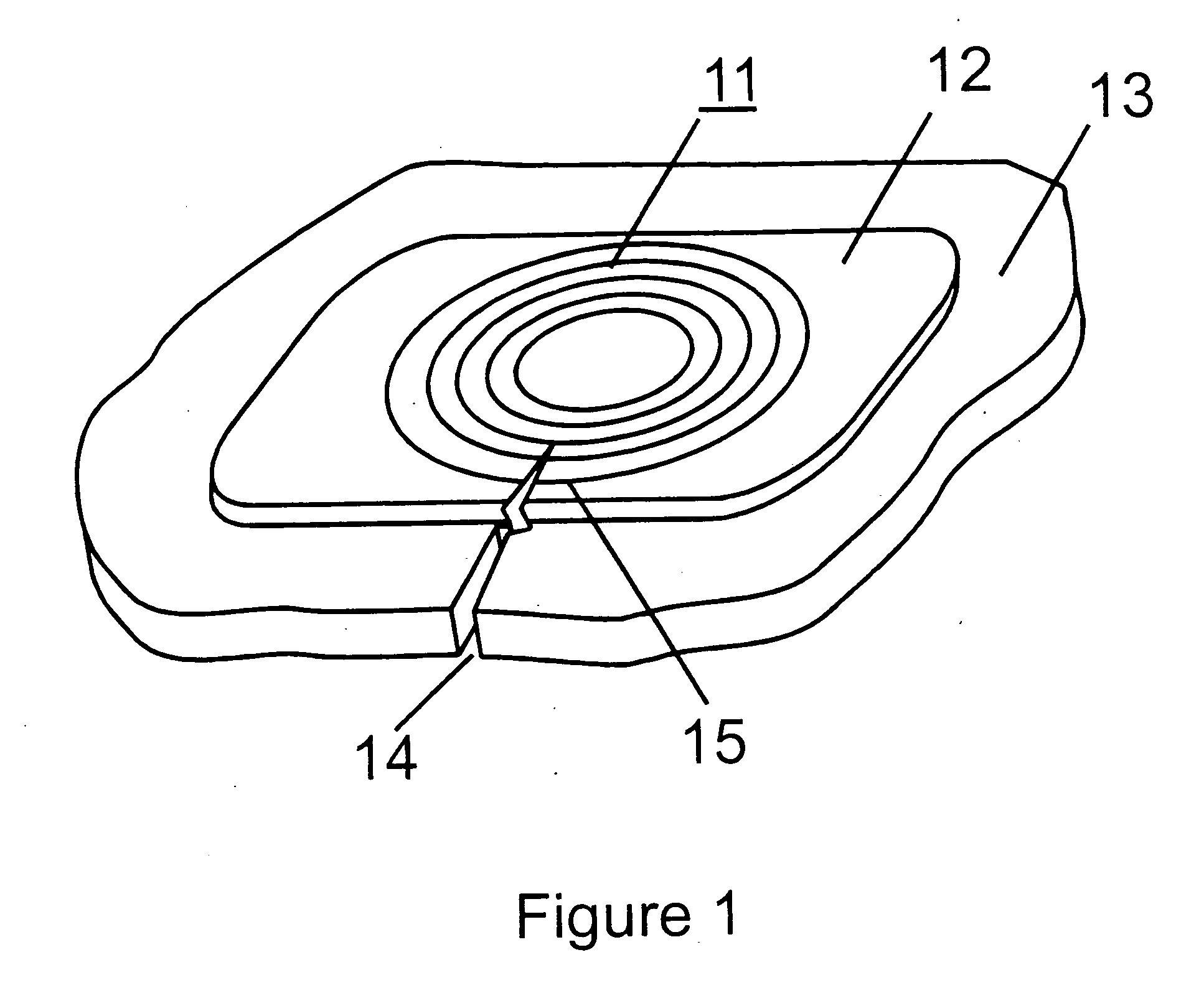
[0017]FIG. 1 shows the preferred embodiment of the crack sensor. The sensor consists of a number of concentric metal rings 11 that are built upon an insulating substrate 12. The rings and substrate are bonded to the structural material 13[,] under test. The rings are designed to break when a crack in the structural material propagates below them. This is accomplished by ensuring that for a critical crack size the stress within the structural material exceeds the critical strain energy release rate of the adhesive / crack sensor system. The strain energy release rate of the sensor system therefore must be lower than that of the structural material. First, to ensure that cracks couple with the sensor, allowing detection, and second, to reduce the probability of a crack nucleation site arising in the sensor from propagating to the composite matrix. If a crack 14 is produced in the structural material, one or more of the metal rings such as 15 will break causing an open circuit in that ri...


PUM

PropertyMeasurementUnit
frequencyaaaaaaaaaa
resonant frequencyaaaaaaaaaa
phase/frequencyaaaaaaaaaa

Abstract

A non-contacting sensor based on inductive coupling for detecting failure initiation, and crack propagation in composite materials is disclosed. A very low cost crack sensing transducer or test pattern that can be imbedded into a structural material, interrogated, and powered wirelessly is described. A detection method for interrogating the crack sensor utilizing RF inductive coupling is disclosed. The proposed sensor consists of minimal components resulting in maximum reliability.

Description

BACKGROUND OF THE INVENTION [0001] 1. Field of the Invention [0002] This invention relates to detecting cracks and structural integrity of materials using a remote wireless sensor. [0003] 2. Description of the Prior Art [0004] Cracks in structural materials can be detected in many ways. Optical fibers are useful as strain gauges because their long length makes them amendable to detecting strain over wide areas [1]. Disadvantages of using optical fibers are that they are expensive to incorporate into the composite structure, and may additionally degrade material integrity [2]. Frequency response methods can be used to detect a change in stiffness of the structure by measuring a shift in natural frequencies when the structure has been damaged. Ultrasonic and X-Radiography are also used to characterize structural materials, but require access to both the front and back of the structure under test as well as the use of bulky equipment. Composite materials are not isotropic, making corre...

Claims


Application Information

Patent Timeline
Patent Type & Authority Applications(United States)
IPC IPC(8): G01N35/00G01N19/08G01N3/00G01N3/06G01N29/04
CPCG01M5/0033G01M5/0083G01N35/00871G01N2203/0062G01N2203/0617
Inventor DENIS, KEVIN L.
Owner XENOTRAN
Why Eureka
Try Eureka