
Cyclone separation dust cup and vacuum cleaner using the same

a vacuum cleaner and cyclone technology, applied in the direction of auxillary pretreatment, cleaning filter means, separation processes, etc., can solve the problems of clogging the conical filter screen cover, the dust cup is poor at separating and filtering impurities in the dust with lighter weight, and the dust cup is poor at separating and filtering impurities with lighter weight, etc., to achieve smooth internal air current, reduce power consumption of vacuum motor, and improve the effect of airflow

Inactive Publication Date: 2012-11-06
SUZHOU KINGCLEAN FLOORCARE
View PDF7 Cites 9 Cited by
  • Summary
  • Abstract
  • Description
  • Claims
  • Application Information

AI Technical Summary

Benefits of technology

[0010]Another purpose of the present invention is to provide a vacuum cleaner using the above-mentioned cyclone separation dust cup. This vacuum cleaner includes a floor brush; the cyclone tube of the cyclone separation dust cup, fixed at the upper part of the cup body, is positioned transversely relative to the cup body; and the cup body is positioned vertically and fixed onto the floor brush. Because the cyclone tube is positioned transversely relative to the cup body, dust filtered away by the cyclone will fall lengthways into the internal cup cavity under gravity when the cup body is installed perpendicularly on the vacuum cleaner, without obstructing the air current flowing out transversely in the cyclone tube. Therefore, when such a vacuum cleaner is working, its internal air current is smoother, the wind velocity higher, and power consumption of the vacuum motor decreased greatly.
[0011]Besides, as in the above-mentioned vacuum cleaner, an HEPA filter device can further be provided at the downstream site of the air outlet on the cup body, so as to perform secondary filtering on the air exhausted out of the cup body and improve the dust filtering quality.
[0013]1. This cyclone separation dust cup of the present invention, with the dust storage cavity communicating with the air exhaust pipe, enables part of the air current entering the cyclone tube to enter the dust storage cavity in the cup body, thus producing a suction in the ash ejection outlet of the cyclone tube that can inhale the dust into the dust storage cavity. This makes the impurities with lighter weight (e.g. hair and downy floc), which cannot fall into the dust storage cavity under gravity, be inhaled into the dust storage cavity successfully, thus greatly improving the separating and filtering effect of this cyclone separation dust cup.
[0014]2. In this cyclone separation dust cup of the present invention, with the cyclone tube further positioned transversely relative to the cup body, the dust filtered away by the cyclone will fall lengthways into the internal cup cavity under gravity when the cup body is installed perpendicularly on the vacuum cleaner, without obstructing the air current flowing out transversely in the cyclone tube. Compared with the prior cyclone separation dust cup, this cyclone separation dust cup of the present invention can make the air current in the vacuum cleaner smoother, the wind velocity higher, and thus the power consumption of the vacuum motor in the vacuum cleaner decreased greatly.
[0015]3. Meanwhile the present invention provides a vacuum cleaner using the above-mentioned cyclone separation dust cup. This vacuum cleaner is not only good at dust separating and filtering, but also smooth in the air current, high in the wind velocity, and lower in the power consumption of the internal vacuum motor.

Problems solved by technology

However, the prior cyclone separation dust cup is poor at separating and filtering impurities in the dust with lighter weight (e.g. hair and downy floc).
It is because such impurities (e.g. hair and downy floc), although separated away under the centrifugal force, cannot fall into the dust storage cavity of the cup body successfully under gravity like those impurities with larger grain size due to their weighing so light themselves, and can only hover afloat in the cyclone tube with the air current.
This will not only prevent other impurities from being filtered away, but also usually intercepted by the conical filter screen cover, which will result in clogging of the conical filter screen cover, unsmoothness of the air current, and even increase of power consumption of the vacuum motor of the vacuum cleaner.

Method used


Image

  • Cyclone separation dust cup and vacuum cleaner using the same
  • Cyclone separation dust cup and vacuum cleaner using the same
  • Cyclone separation dust cup and vacuum cleaner using the same

Examples


Embodiment Construction

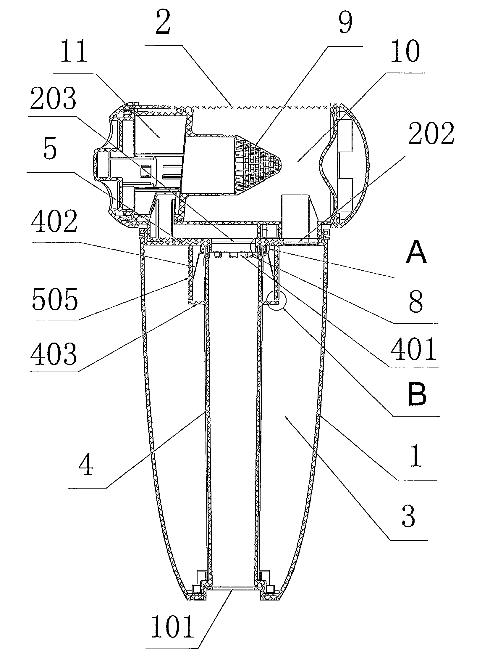
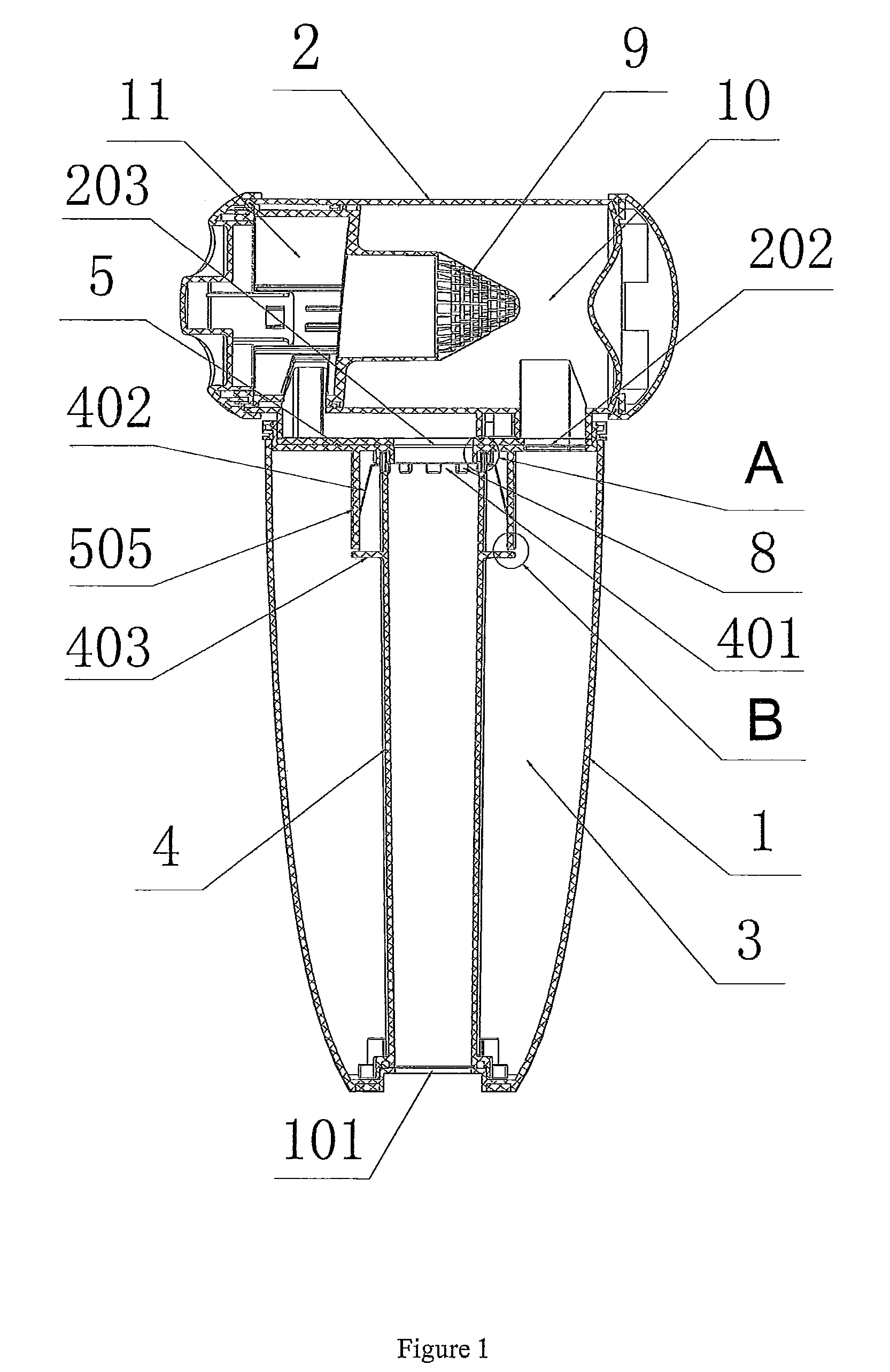
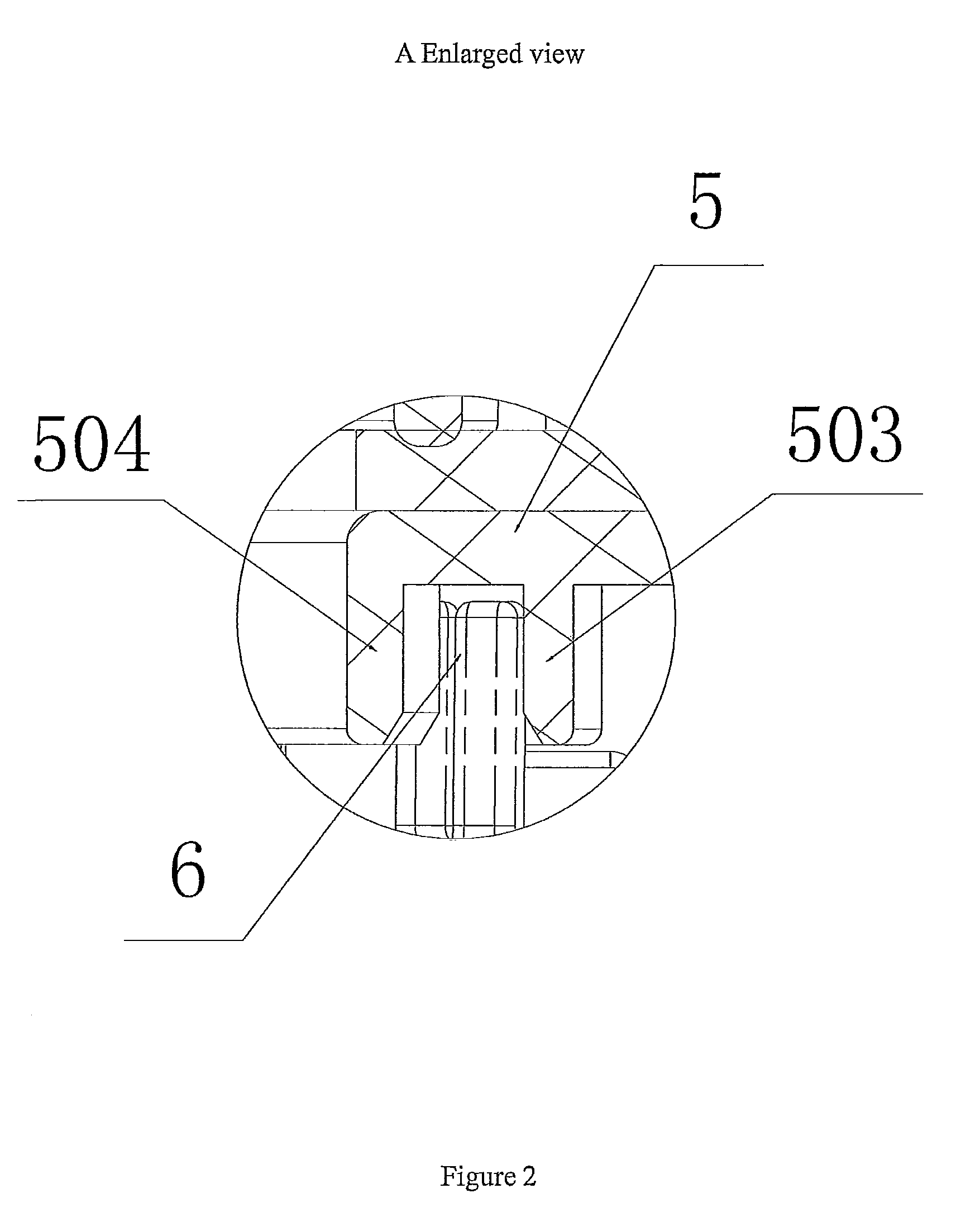
[0025]Embodiment: An embodiment of the cyclone separation dust cup of the present invention, as shown in FIGS. 1 to 6, includes a cup body 1 and a cyclone tube 2. The cyclone tube 2, fixed above the cup body 1 through a connection support 5, is positioned transversely relative to the cup body 1 (which means the axis of the cyclone tube 2 is perpendicular to the axis of the cup body 1). The cup body 1 is provided at the bottom with an air outlet 101, and the cyclone tube 2 is provided on the tube body with an air inlet 201, an ash ejection outlet 202, and an air exhaust outlet 203. In the tube body is fixed a conical filter screen cover 9 dividing the internal tube cavity into a cyclone cavity 10 and an air exhaust cavity 11. The air inlet 201 communicates with the environment and the cyclone cavity 10. The ash ejection outlet 202 communicates with the cyclone cavity 10 and a dust storage cavity 3 positioned in the cup body 1. The air exhaust outlet 203 communicates with the air outl...


PUM

PropertyMeasurementUnit
centrifugal forceaaaaaaaaaa
weightaaaaaaaaaa
grain sizeaaaaaaaaaa

Abstract

A cyclone separation dust cup, which includes a cup body and a cyclone tube, the cyclone tube being provided with an air inlet, an ash ejection outlet, and an air exhaust outlet; and the ash ejection outlet communicates with a dust storage cavity in the cup body, the air exhaust outlet with an air outlet positioned on the cup body through an air exhaust pipe, and the dust storage cavity with the air exhaust pipe. The dust storage cavity, by communicating with the air exhaust pipe, enables part of the air current entering the cyclone tube to enter the dust storage cavity in the cup body, thus producing suction in the ash ejection outlet of the cyclone tube that can draw the dust into the dust storage cavity. This enables the impurities with a lighter weight (e.g. hair and downy floc), which cannot fall into the dust storage cavity under gravity, to be inhaled into the dust storage cavity successfully, thus greatly improving the separating and filtering effect of this cyclone separation dust cup.

Description

FIELD OF THE INVENTION[0001]The present invention relates to a cyclone separation dust cup and a vacuum cleaner using the same.BACKGROUND OF THE INVENTION[0002]A cyclone separation dust cup is a device that separates dust by making use of the centrifugal force. It is provided inside with a cyclone tube, which is provided at the side tube body with an air inlet in the tangent direction. Dust-laden air performs spiral movement after entering the cyclone tube through this air inlet, which makes most of the dust ejected out in the tangent direction under the centrifugal force and fall into a dust storage cavity in the cup body. Then the air enters an air exhaust pipe through a conical filter screen cover, and is finally exhausted out of the dust cup.[0003]However, the prior cyclone separation dust cup is poor at separating and filtering impurities in the dust with lighter weight (e.g. hair and downy floc). It is because such impurities (e.g. hair and downy floc), although separated away...

Claims


Application Information

Patent Timeline
Patent Type & Authority Patents(United States)
IPC IPC(8): A47L9/10A47L9/20
CPCA47L9/1683
Inventor NI, ZUGEN
Owner SUZHOU KINGCLEAN FLOORCARE
Learn More