Three dimensional driving scheme for electrophoretic display devices

a display device and three-dimensional technology, applied in the direction of electric digital data processing, instruments, computing, etc., can solve the problem of little freedom for a display engineer to perform color mapping of an electrophoretic display

Active Publication Date: 2014-03-25
E INK CORPORATION
View PDF19 Cites 145 Cited by
  • Summary
  • Abstract
  • Description
  • Claims
  • Application Information

AI Technical Summary

Benefits of technology

[0027]The present driving method has the advantage that the brightness (e.g., grayscale) and color intensity of the images may be separately tuned.

Problems solved by technology

As a result, the color intensity (i.e., saturation) and the brightness (i.e., reflectance) of the images displayed cannot be tuned separately, which allows very little freedom for a display engineer to perform color mapping of an electrophoretic display.

Method used


Image

  • Three dimensional driving scheme for electrophoretic display devices
  • Three dimensional driving scheme for electrophoretic display devices
  • Three dimensional driving scheme for electrophoretic display devices

Examples


Embodiment Construction

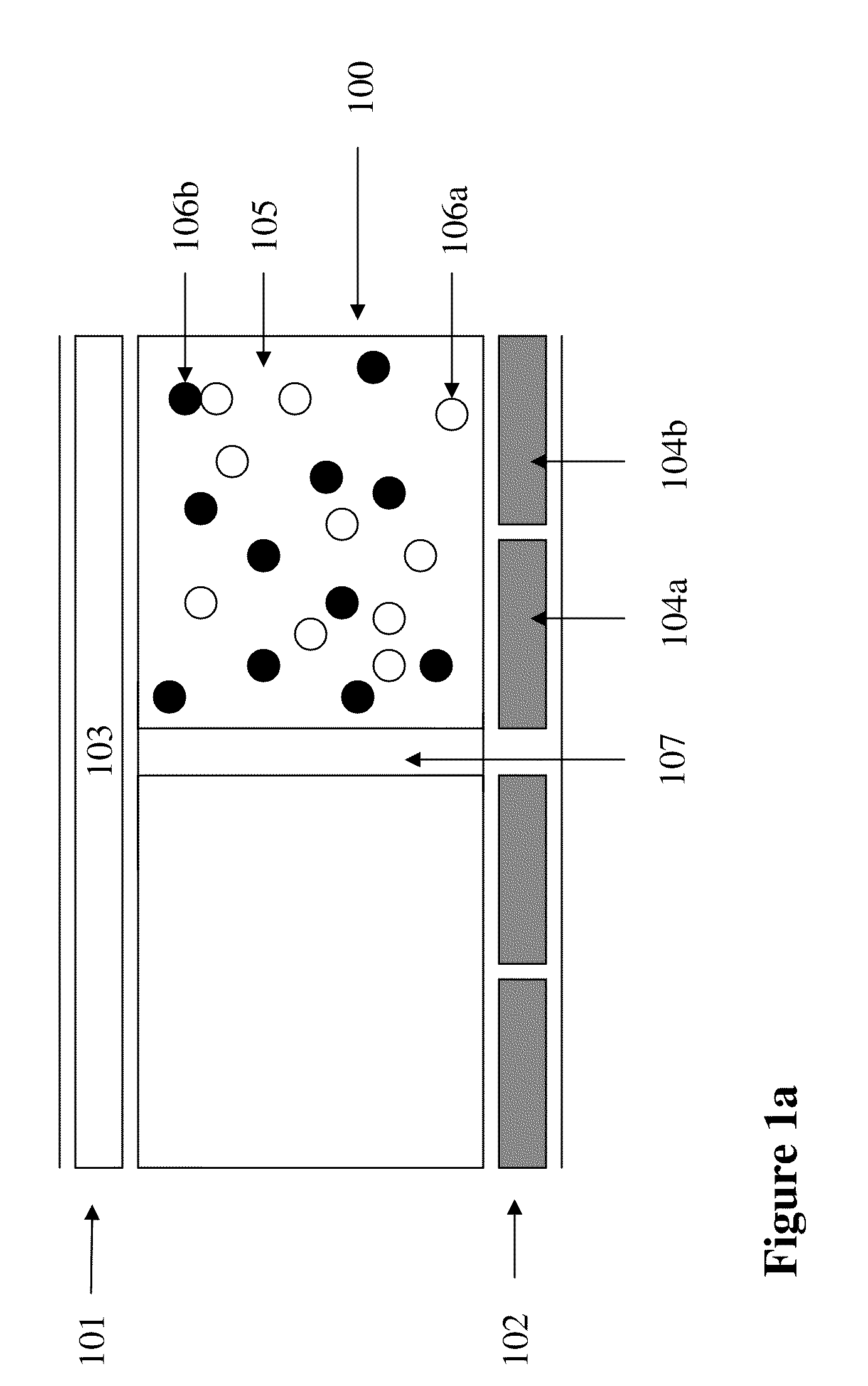
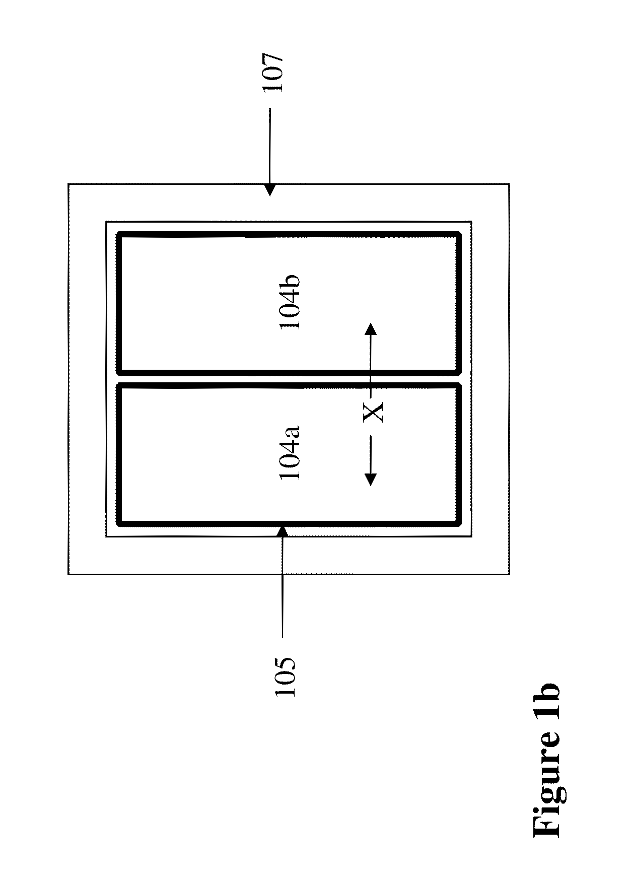
[0036]FIG. 1a depicts a cross-section view of a display device. A display cell (100) is sandwiched between a first layer (101) and a second layer (102). The display cell (100) is surrounded by partition walls (107). The first layer comprises a common electrode (103). The second layer comprises at least two pixel electrodes (104a and 104b).

[0037]The display cell (100) is a micro-container filled with a display fluid (105). It is understood that, in the context of the present invention, the term “display cell” is intended to encompass any micro-containers (e.g., microcups, microcapsules, microchannels or conventional partition type display cells), regardless of their shapes or sizes, as long as they perform the intended functions.

[0038]The display fluid (105) may be an electrophoretic fluid comprising at least two types of movable species. In one embodiment, the fluid comprises two types of pigment particles (106a and 106b) of different colors. For example, the two types of charged pi...


PUM

PropertyMeasurementUnit
particle sizeaaaaaaaaaa

Abstract

The present invention is directed to a driving method, in particular a three dimensional driving scheme for electrophoretic display devices. The method comprises applying a driving step in each of at least two electric fields to drive two types of pigment particles of different colors laterally and / or vertically for separately adjusting the grayscale and / or colors of the display. The present driving method has the advantage that the brightness and color intensity of the images may be separately tuned.

Description

[0001]This application claims priority to U.S. Provisional Application No. 61 / 362,683, filed Jul. 8, 2010; the content of which is incorporated herein by reference in its entirety.FIELD OF THE INVENTION[0002]The present invention is directed to a driving method, in particular a three dimensional driving scheme for electrophoretic display devices.BACKGROUND OF THE INVENTION[0003]An electrophoretic display (EPD) is a non-emissive device based on the electrophoresis phenomenon influencing charged pigment particles dispersed in a dielectric solvent. An EPD typically comprises a pair of spaced-apart plate-like electrodes. At least one of the electrode plates, typically on the viewing side, is transparent. An electrophoretic fluid composed of a dielectric solvent with charged pigment particles dispersed therein is enclosed between the two electrode plates.[0004]An electrophoretic fluid may have one type of charged pigment particles dispersed in a solvent or solvent mixture of a contrastin...

Claims


Application Information

Patent Timeline
Patent Type & Authority Patents(United States)
IPC IPC(8): G09G5/10G02F1/167G02F1/16762G02F1/1685
CPCG09G3/3446G02F2202/36G02F2001/1676G09G2300/0426G02F1/167G09G2310/061G02F1/1685G02F1/16762
Inventor YANG, BO-RULIU, YING-TSANGWEI, CHUN-ANLIN, CRAIG
Owner E INK CORPORATION
Why Eureka
Try Eureka