Solid free-form fabrication methods for the production of dental restorations

a dental restoration and solid free-form technology, applied in the field of dental restorations, can solve the problems of affecting strength and reliability, reducing skill time, and requiring extensive labor and time for the fabrication of current all-ceramic dental restorations, and achieving the effect of promoting powder particle binding

Inactive Publication Date: 2005-02-03
IVOCLAR VIVADENT AG
View PDF99 Cites 360 Cited by
  • Summary
  • Abstract
  • Description
  • Claims
  • Application Information

AI Technical Summary

Benefits of technology

[0010] Three-dimensional printing is used to create a dental restoration by ink-jet printing a binder into selected areas of sequentially deposited layers of powder. Each layer is created by spreading a thin layer of powder over the surface of a powder bed. Instructions for each layer may be derived directly from a CAD representation of the restoration. The area to be printed is obtained by computing the area of intersection between the desired plane and the CAD representation of the object. All the layers required for an aesthetically sound restoration can be deposited concurrently slice after slice and sintered / cured simultaneously. The amount of green body oversize is equivalent to the amount of shrinkage which occurs during sintering or curing. While the layers become hardened or at least partially hardened as each of the layers is laid down, once the desired final shaped configuration is achieved and the layering process is complete, in some applications it may be desirable that the form and its contents be heated or cured at a suitably selected temperature to further promote binding of the powder particles. The individual sliced segments or layers are joined by one or more binders to form the three dimensional structure. The unbound powder supports temporarily unconnected portions of the component as the structure is built but is removed after completion of printing.

Problems solved by technology

The fabrication of current all-ceramic dental restorations often requires extensive labor and time and the proficiency of highly skilled technicians.
Many state-of-the-art dental restorations reveal a sense of artistry that can typically only be achieved manually or “by hand.” While aesthetics are preserved with this process, microstructural inhomogeneities may appear, affecting strength and reliability.
Although pressable crowns reduce some of the skill time required, about two hours of concerted effort is necessary to complete a crown.
Pressed crowns may also suffer from similar strength and reliability problems typical of “hand made” crowns.
However, the necessary machining steps limit the choice of materials that can be used in dental restorations and sometimes compromise the strength and / or aesthetics of the finished restoration.
One of the current limitations of the CAD / CAM approach, which is not easy to overcome, is the fact that currently available systems at best produce copings that require veneering layers to provide a natural appearance.
Consequently, final processing of the crown is still in the hands of dental technicians which may limit the resulting structural reliability of the restoration.
The existing commercial CAD / CAM systems are unable to produce full crowns.
Some of the systems can machine inlays / onlays from a solid ceramic block and are not able to produce crowns or even copings.
This is an automation of steps that are otherwise performed by dental technicians and very well may not be practically advantageous.
One of the key limitations intrinsic to CAM methods is the fact that machining is not competitive technology for mass production of parts and components of any kind including dental restorations, e.g. dentures and crowns.

Method used


Image

  • Solid free-form fabrication methods for the production of dental restorations
  • Solid free-form fabrication methods for the production of dental restorations
  • Solid free-form fabrication methods for the production of dental restorations

Examples


example 1

[0084] Filament is prepared from Investment Casting Wax (ICW06, Stratasys) and thermoplastic ABS (P400, Stratasys) and equiaxed alumina powder of 5 to 10 microns particle size. The binder content is about 30 volume percent.

[0085] Using a CAD / CAM device and digitizer manufactured by CAD / CAM Ventures (Irving, Tex.), the model of a tooth preparation is digitized and the obtained CAD file is used in conjunction with an FDM2000 fused deposition modeling machine available from Stratasys Inc. (Eden Prairie, Minn.). Using the filament containing equiaxed alumina powder in a thermoplastic matrix, single and multiunit dental restorations are formed and then subjected to binder-removal and soft-sintering cycles. The resulting porous preforms are infiltrated with glass using materials supplied by Vita Zahnfabrick (Bad Sackingen, Germany) and glass infiltration techniques used for Vita In-Ceram Alumina restorations.

example 2

[0086] The same CAD file as used in Example 1 is used in conjunction with a three-dimensional printing machine such as the Z402 System available from Z Corporation (Mass.) to print on ceramic powder and on metal powder separately. The same powder-binder mixture used above is used herein as the powder layer. A binder mixed with finely dispersed pigments is printed on the powder layer. Successive layers are deposited to form a dental restoration based on the CAD file. After the restoration is fully formed, the binder is burned out and glass is then infiltrated into the interstices. The pigment is retained in interstitial sites between the alumina particles to impart a shade to the composite.

example 3

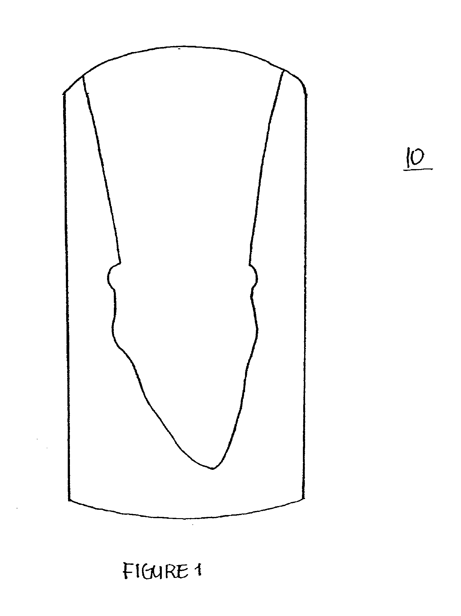
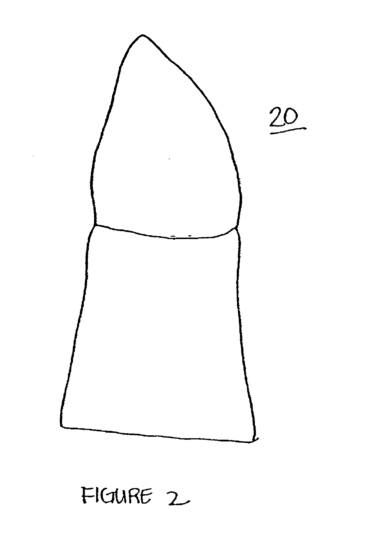
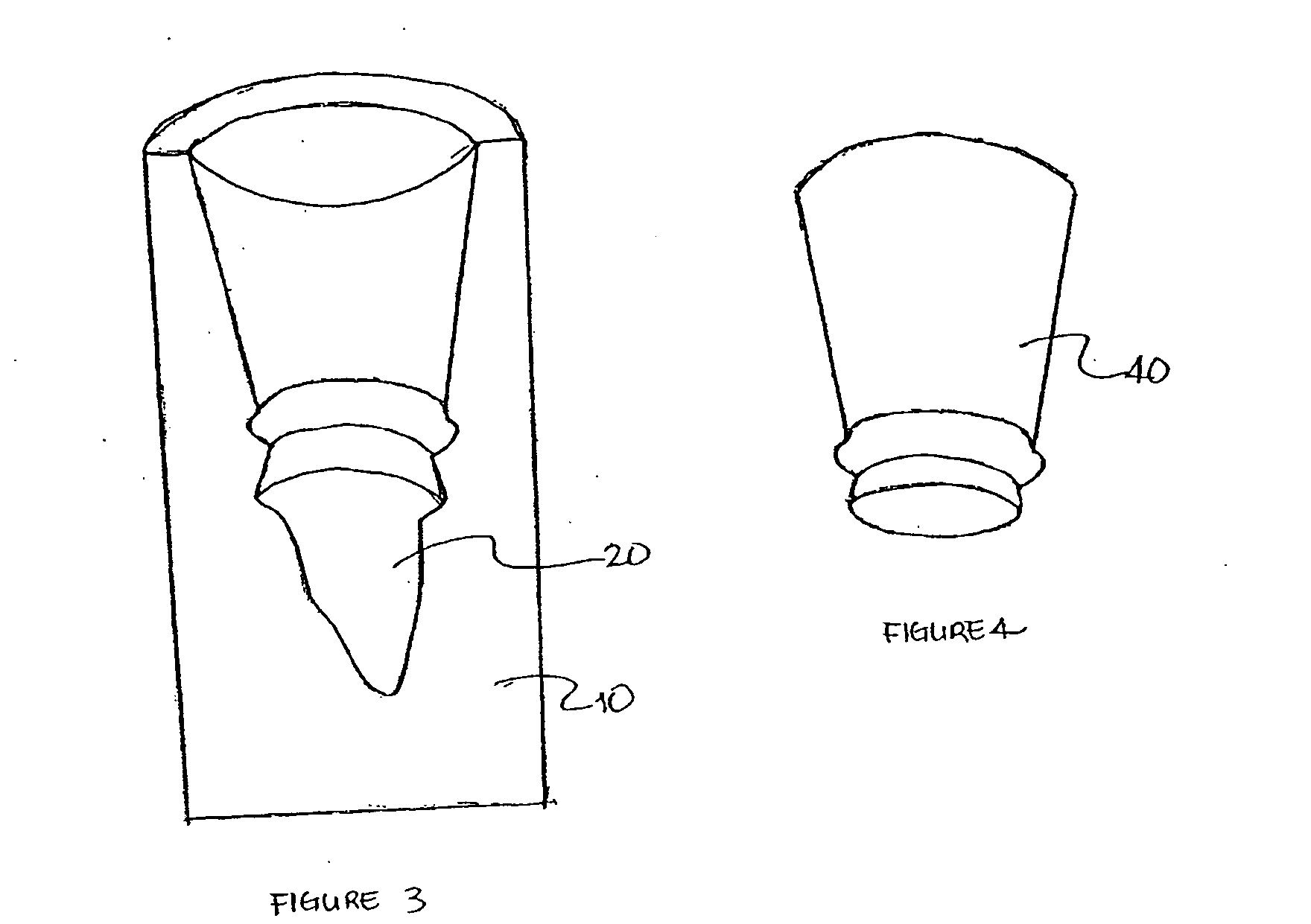
[0087] Using a CAD / CAM device and digitizer manufactured by CAD / CAM Ventures (Irving, Tex.), the model of a tooth preparation is digitized and the obtained CAD file is used to manufacture a shell. The CAD file is modified to provide a thickness in the shell great enough to support and withstand the refractory materials. The thickness of the shell varies from about 0.5 to about 10 mm in thickness. The shell produced is thinner near the margin and thicker near the apex. This information is fed into a computerized liquid wax dispensing machine. A green injection wax available from Romanoff Inc. is injected into the machine. The wax is delivered as tiny beads in liquid state that solidify shortly after dispensing. The internal surface of the shell is smooth. The support structure of the shell is in the form of a solid or void-containing structure, such as a honeycomb structure. Polyvest refractory material available from WhipMix corporation is poured into the shell and sets. After setti...


PUM

PropertyMeasurementUnit
timeaaaaaaaaaa
thicknessaaaaaaaaaa
droplet sizesaaaaaaaaaa

Abstract

Solid free form fabrication techniques can be utilized indirectly to manufacture substrates, dies, models, near-net shapes, shells, and wax-ups that are then used in the manufacture of dental articles. Digital light processing is the most preferred indirect method for the production of substrates. After the substrates are produced, various coating or deposition techniques such as gel casting, slip casting, slurry casting, pressure infiltration, dipping, colloidal spray deposition or electrophoretic deposition are used to manufacture the dental article.

Description

CROSS-REFERENCE TO RELATED APPLICATIONS [0001] This application is a continuation-in-part application of U.S. application Ser. No. 10 / 053,430, filed Oct. 22, 2001, which is a continuation-in-part application of U.S. application Ser. No. 09 / 946,413 filed Sep. 5, 2001 which is a continuation-in-part of U.S. application Ser. No. 09 / 350,604 filed Jul. 9, 1999, now U.S. Pat. No. 6,322,728, which claims priority to U.S. Provisional Application Ser. No. 60 / 092,432 filed on Jul. 10, 1998, and is a continuation-in-part application of U.S. application Ser. No. 10 / 027,017 filed Dec. 18, 2001, which is a divisional of U.S. application Ser. No. 09 / 376,921, filed Aug. 18, 1999, now U.S. Pat. No. 6,354,836, which claims priority to U.S. Provisional Application No. 60 / 097,216, filed Aug. 20, 1998, and is a continuation-in-part application of U.S. application Ser. No. 10 / 857,482, filed May 28, 2004, which claims priority to U.S. Provisional Application No. 60 / 474,166, filed May 29, 2003, all of whic...

Claims


Application Information

Patent Timeline
Patent Type & Authority Applications(United States)
IPC IPC(8): A61C5/77A61C13/00A61K6/06A61K6/083A61K6/838A61K6/884A61K6/891A61K6/893
CPCA61C13/0003A61C13/0004B29C67/0081B29C67/0077A61K6/09A61K6/087A61K6/083A61C13/0019A61K6/0205A61K6/0215A61K6/0235A61K6/024A61K6/025A61K6/033A61K6/04A61K6/06A61K6/08C08L33/08C08L63/00C08L83/04B29C64/153B29C64/165B33Y80/00B33Y10/00A61C5/77A61C5/35A61K6/807A61K6/816A61K6/822A61K6/802A61K6/849A61K6/818A61K6/838A61K6/893A61K6/84A61K6/884A61K6/891A61K6/887
Inventor BRODKIN, DMITRIPANZERA, CARLINOPRASAD, ARUNDAY, GRANT P.BORENSTEIN, STEFAN
Owner IVOCLAR VIVADENT AG
Why Eureka
Try Eureka