Electronic paper display device, manufacturing method and driving method thereof

a technology of electronic paper and display device, which is applied in the direction of static indicating device, optics, instruments, etc., can solve the problems of lowering response speed, difficult to display moving pictures, and complex process, and achieves the effect of more rapid response speed

Inactive Publication Date: 2010-07-06
LG ELECTRONICS INC
View PDF5 Cites 334 Cited by
  • Summary
  • Abstract
  • Description
  • Claims
  • Application Information

AI Technical Summary

Benefits of technology

[0020]An object of the present invention is to provide an electronic paper display device, a manufacturing method and a driving method thereof wherein the internal voltage of driving devices to drive the electronic paper display device is reduced, and the driving devices are operated at more rapid response speed.

Problems solved by technology

However, this structure is a wet-type structure in which the response speed is decreased to approximately 100 ms due to the viscous resistance of the liquid, and therefore, it is difficult to display moving pictures.
As a result, the process is complicated.
Furthermore, time necessary to generate the driving voltage pulse having the large voltage level is increased with the result that the response speed is lowered.

Method used


Image

  • Electronic paper display device, manufacturing method and driving method thereof
  • Electronic paper display device, manufacturing method and driving method thereof
  • Electronic paper display device, manufacturing method and driving method thereof

Examples


Embodiment Construction

[0052]Reference will now be made in detail to the preferred embodiments of the present invention, examples of which are illustrated in the accompanying drawings. Wherever possible, the same reference numbers will be used throughout the drawings to refer to the same or like parts.

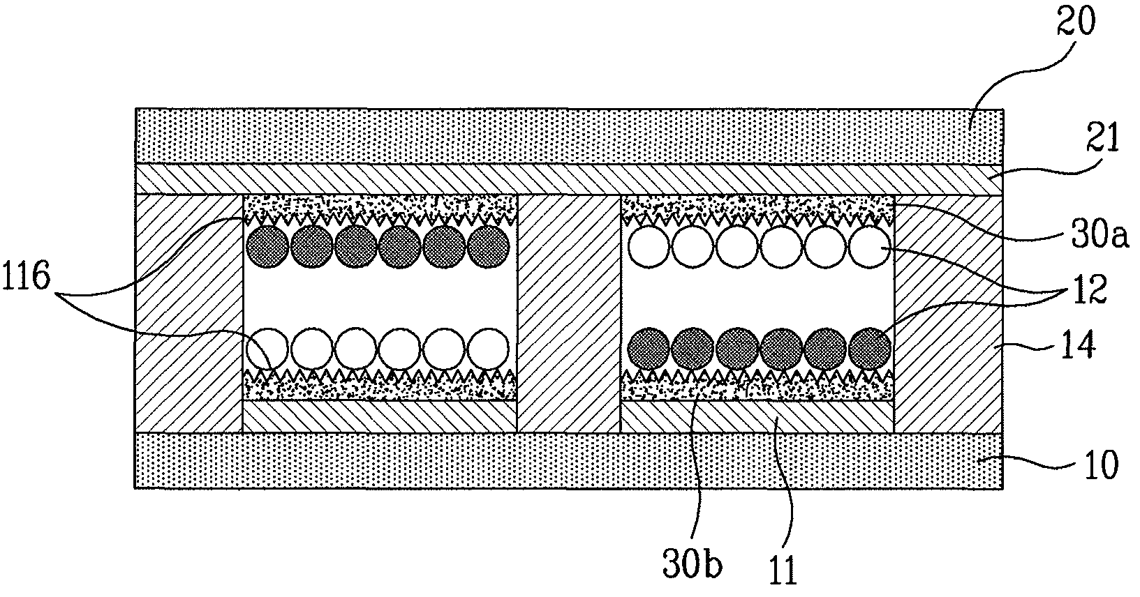
[0053]FIG. 4 is a sectional view illustrating an electronic paper display device according to an embodiment of the present invention. As shown in FIG. 4, the electronic paper display device includes: a first structure having a first substrate 20, a first electrode 21 formed at the bottom of the first substrate 20, and a first micro protrusion member 30a formed at the bottom of the first electrode 21; a second structure, which is disposed opposite to the first structure while the second structure is spaced a predetermined distance from the first structure, having a second substrate 10, a second electrode 11 formed at the top of the second substrate 20, and a second micro protrusion member 30b formed at the to...


PUM

PropertyMeasurementUnit
sizeaaaaaaaaaa
thicknessaaaaaaaaaa
diameteraaaaaaaaaa

Abstract

An electronic paper display device, a manufacturing method and a driving method thereof are disclosed. Micro protrusion members are formed at electrodes or at insulating layers. Consequently, the electrophoretic particles are prevented from being securely attached to an upper or the lower structure, and therefore, the quality of pictures is improved, and the contrast ratio of the pictures is increased. The relative sizes and the injection amounts of two kinds of electrophoretic particles are changed such that the relative sizes and the injection amounts of the electrophoretic particles are different from each other. Consequently, the driving voltage is lowered by excessively electrifying the electrophoretic particles of one kind. Protrusions are formed at the corresponding electrode such that a relatively large electric field is distributed around the electrode at which electrophoretic particles are located in the initial stage of voltage application. Consequently, the electrophoretic particles are easily separated from the electrode and moved even at low driving voltage. As such, the voltage level of the driving voltage pulse is lowered. Consequently, it is possible to further increase the response speed of the driving devices and to lower the internal voltage of the devices, thereby reducing the costs related to the driving devices.

Description

[0001]This application claims the benefit of Korean Patent Application Nos. 10-2005-0078777, filed on Aug. 26, 2005, 10-2005-0097249, filed on Oct. 15, 2005, 10-2005-0095507, filed on Oct. 11, 2005, 10-2005-0093434, filed on Oct. 5, 2005 which is hereby incorporated by reference as if fully set forth herein.BACKGROUND OF THE INVENTION[0002]1. Field of the Invention[0003]The present invention relates to an electronic paper display device, a manufacturing method and a driving method thereof.[0004]2. Discussion of the Related Art[0005]An electronic paper display device is a core device to realize a flexible display. The electronic paper display device is based on electrophoresis in which an electromagnetic field is applied to a conductive material such that the conductive material has mobility. Micro particles having conductivity are distributed between thin-type flexible substrates, and positions of the micro particles (or toner particles) are changed due to the change of the polariti...

Claims


Application Information

Patent Timeline
Patent Type & Authority Patents(United States)
IPC IPC(8): G02B26/00G09G3/34G02F1/167G02F1/1676
CPCG02F1/167G09G3/344G02F1/133345G02F2001/1676G09G2320/0252G02F1/1676
Inventor SONG, MOON BONG
Owner LG ELECTRONICS INC
Why Eureka
Try Eureka