Construction of electrophoretic displays

a technology of electrophoretic display and construction, which is applied in the direction of static indicating device, separation process, instruments, etc., can solve the problems of preventing their widespread use, inadequate service life of these displays, and the presence of such a polymeric binder in the final display

Active Publication Date: 2006-01-17
E INK CORPORATION
View PDF143 Cites 345 Cited by
  • Summary
  • Abstract
  • Description
  • Claims
  • Application Information

AI Technical Summary

Benefits of technology

[0052]means for applying a voltage to the at least one electrode and thereby moving the particles between a first position, in which the particles are dispersed through the cavity, thereby preventing light from passing through the cavity, and a second position, in which the particles lie adjacent the at least one electrode, thereby permitting light to pass through the cavity.

Problems solved by technology

Nevertheless, problems with the long-term image quality of these displays have prevented their widespread usage.
For example, particles that make up electrophoretic displays tend to settle, resulting in inadequate service-life for these displays.
Although provision of a solid polymeric binder around the capsules in such a display is effective in forming the capsules into a layer with substantial mechanical cohesion, the presence of such a polymeric binder in the final display does give rise to certain problems, especially when the display is to be used for an extended period of perhaps several years.
A further problem with electrophoretic displays using polymeric binders is that such displays are thermodynamically only metastable.
For example, many polymeric binders have a substantial capacity to absorb hydrocarbon solvents, so there is a tendency for such solvents to migrate from within the capsules into the polymeric binder, with resultant changes in the electrical properties of the binder.
Although the amounts of such small molecules migrating into the suspending fluid are small, they can potentially have substantial effects upon the electrophoretic properties of the particles in the suspending fluid; the electrophoretic properties of the particles depend upon maintenance of relatively small charges on the particles, and even minute amounts of some small molecules, and especially ionic species, can have significant effects on the charges of the particles.

Method used


Image

  • Construction of electrophoretic displays
  • Construction of electrophoretic displays
  • Construction of electrophoretic displays

Examples


Embodiment Construction

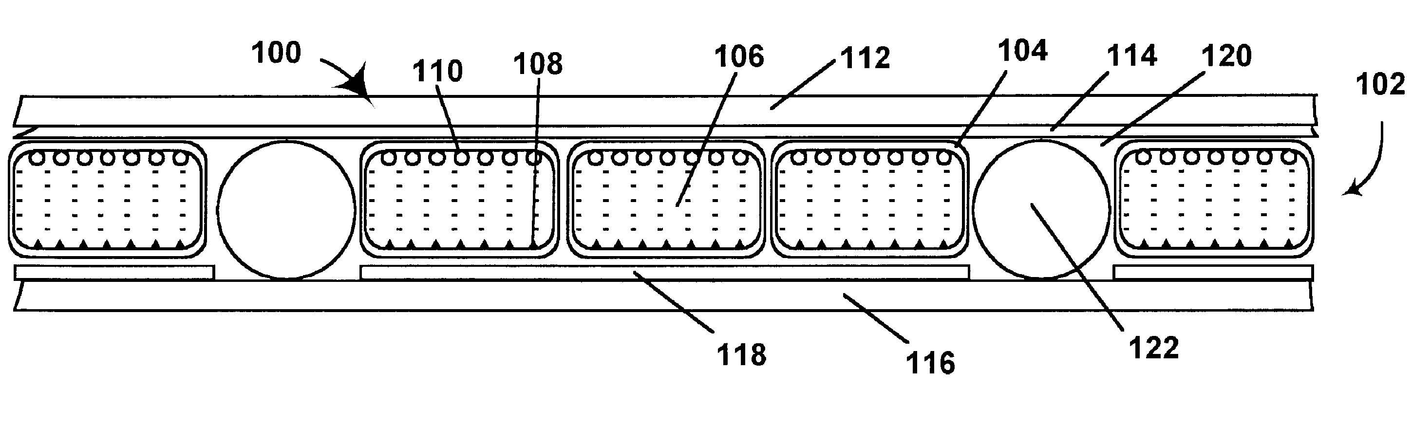
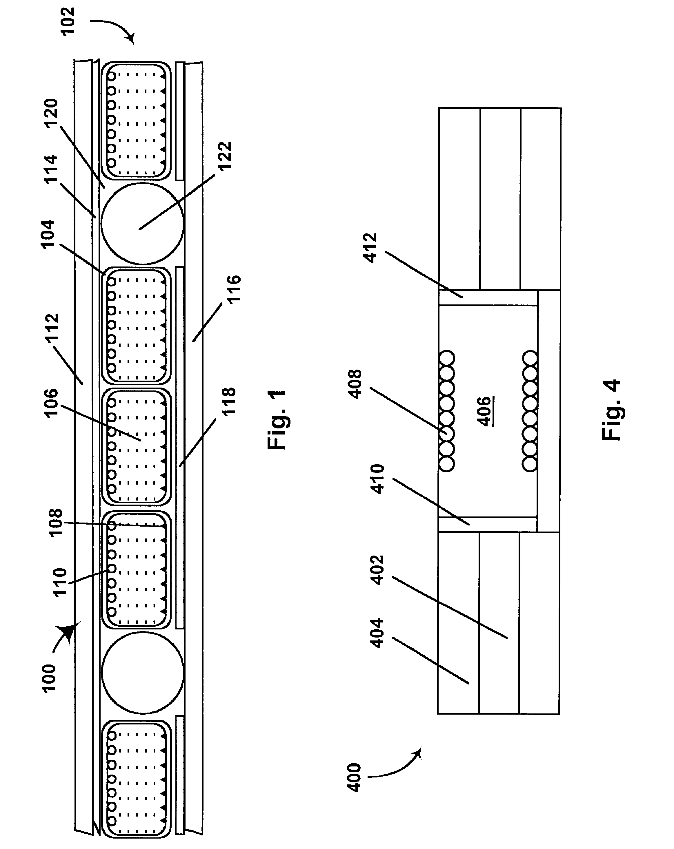
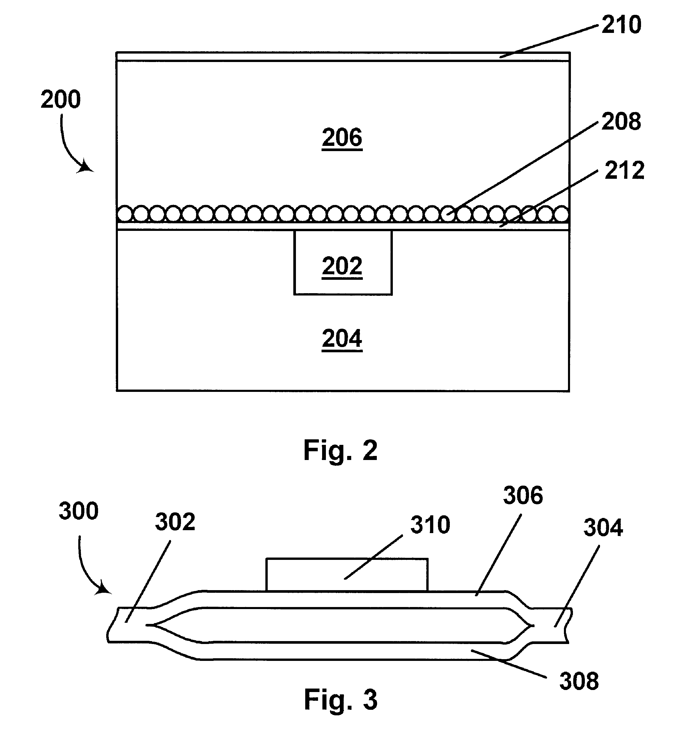
[0058]As already indicated, the present invention has three principal aspects, namely electrophoretic displays using liquid external phases, optical switches using electrophoretic media, and electrophoretic displays having electrodes disposed on side walls extending between the front and rear substrates of the display. These three principal aspects of the present invention will now be discussed separately, although it should be understood that a single apparatus may make use of more than one of these principal aspects; for example, optical switches according to the second principal aspect of the invention may make use of electrophoretic displays having side wall electrodes in accordance with the third principal aspect.

[0059]Section A : Electrophoretic Displays Using Liquid External Phase

[0060]As already indicated, in one principal aspect this invention provides an encapsulated electrophoretic medium comprising a plurality of capsules, each of the capsules comprising a capsule wall, ...


PUM

PropertyMeasurementUnit
electric fieldaaaaaaaaaa
compositionaaaaaaaaaa
viscosityaaaaaaaaaa

Abstract

An electrophoretic display (100) comprises a front light-transmissive substrate (112), a rear substrate (116) spaced from the front substrate (112) so as to leave a cavity, and an electrophoretic medium (102) in the cavity, the electrophoretic medium (102) comprising a liquid external phase (120) and a plurality of capsules (104) suspended in the liquid external phase (120), each of the capsules comprising a capsule wall, a suspending fluid (106) held within the capsule wall and at least one electrically charged particle (108, 110) suspended in the suspending fluid (106).

Description

CROSS REFERENCE TO RELATED APPLICATIONS[0001]This application claims benefit of copending application Ser. No. 60 / 319,919, filed Jan. 31, 2003. The entire contents of this application, and of all United States Patents, published applications and copending applications mentioned below, are herein incorporated by reference.BACKGROUND OF INVENTION[0002]This invention relates to construction of electrophoretic displays. More specifically, this invention relates to (a) encapsulated electrophoretic displays in which a liquid phase is present outside the capsules; (b) an electrophoretic display which serves as an optical switch; and (c) novel arrangements for addressing electrophoretic displays. Some aspects of the invention may be useful in non-electrophoretic electro-optic displays.[0003]The term “electro-optic” as applied to a material or a display, is used herein in its conventional meaning in the imaging art to refer to a material having first and second display states differing in at...

Claims


Application Information

Patent Timeline
Patent Type & Authority Patents(United States)
IPC IPC(8): G02B26/00G01N27/453G09G3/34G02F1/167G02F1/16757G02F1/1677
CPCG02F1/167G02F1/16757G02F1/1677
Inventor PAOLINI, JR., RICHARD J.ZEHNER, ROBERT W.AMUNDSON, KARL R.HERB, CRAIG A.ARANGO, ALEXI C.LOXLEY, ANDREW L.
Owner E INK CORPORATION
Why Eureka
Try Eureka