Electrophoretic device, method of driving electrophoretic device, and electronic apparatus

a technology of electrophoretic devices and electrophoretic devices, applied in the direction of instruments, static indicating devices, etc., can solve the problems of inability to achieve averaging by the naked eye, image appearance is worsened, and is considered to become a big problem, so as to achieve the desired optical characteristics. , the effect of reliable realization

Active Publication Date: 2010-03-16
E INK CORPORATION
View PDF11 Cites 377 Cited by
  • Summary
  • Abstract
  • Description
  • Claims
  • Application Information

AI Technical Summary

Benefits of technology

[0030]Due to the above-mentioned structure, there is an effect that an electrophoretic device which may reliably realize the desired optical characteristics may be provided.
[0032]Due to the above-mentioned structure, there is an effect that the proportion of the pixel number for obtaining the desired optical characteristic may be calculated more accurately.
[0033]Moreover, in the electrophoretic device of the present invention, the electrophoretic particles include a plurality of types of particles having different optical characteristics. Due to the above-mentioned structure, there is an effect that the change in the complex optical characteristic such as brightness or chroma may be expressed.
[0034]Furthermore, the structure may be such that the electrophoretic dispersion liquid is encapsulated in a microcapsule. By filling the electrophoretic dispersion liquid into a microcapsule, spilling of the dispersion liquid during the manufacturing process of the electrophoretic device may be avoided, and precipitation and aggregation of the electrophoretic particles may be reduced.
[0035]Moreover, in the electrophoretic device of the present invention, the pixel electrodes are arranged in matrix form. Due to the above-mentioned structure, there is an effect that images of complex shape may be displayed.
[0038]Due to the above-mentioned structure, there is an effect that a method of driving an electrophoretic device which may reliably realize the desired optical characteristics may be provided.

Problems solved by technology

However, conversely, since the displayed gradation becomes the average value in a certain region as described above, there is a problem in that, if the pixel size is too large, averaging is not performed by the naked eye and the image appearance is worsened.
However, regarding this point, since miniaturization of the pixel size is well advanced due to high quality thin-film circuits, for example represented by a low temperature polysilicon thin-film transistor, it is not considered to become a big problem in the future.
However, there are the following problems in the conventional techniques.
However, actually in some cases, electrophoretic particles overflow the ideally deposited region due to the leakage of the electric field passing through the electrophoretic dispersion liquid.
Consequently, in the actual area gradation, even if the first voltage or the second voltage is appropriately applied to respective pixels in order to obtain the desired proportion of the pixel number of the first optical characteristic state, and the pixel number of the second optical characteristic state, the pixel area ratio in appearance becomes different, causing a problem of inability to obtain the desired optical characteristic.

Method used


Image

  • Electrophoretic device, method of driving electrophoretic device, and electronic apparatus
  • Electrophoretic device, method of driving electrophoretic device, and electronic apparatus
  • Electrophoretic device, method of driving electrophoretic device, and electronic apparatus

Examples


embodiment 1

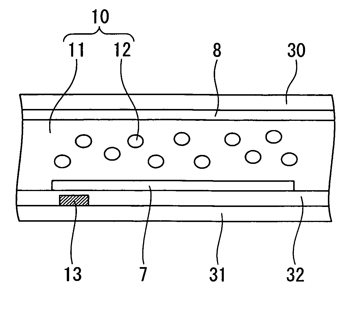
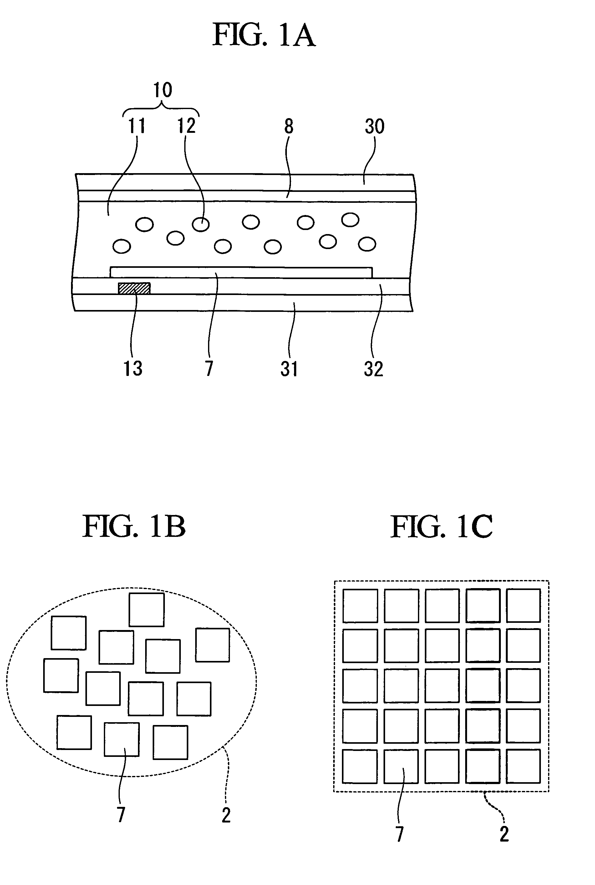
[0062]FIG. 1 shows a first embodiment of an electrophoretic device according to the present invention, wherein FIG. 1A is a sectional view of a pixel, and FIGS. 1B and 1C show the pixel structure.

[0063]As shown in FIG. 1A, the present electrophoretic device includes a first substrate 30, a common electrode 8 formed on the first substrate, a second substrate 31, a insulating layer 32, a pixel electrode 7 arranged on the common electrode side of the second substrate, and a voltage supply circuit 13 which supplies a first voltage or a second voltage to the pixel electrode. The pixel electrode 7 and the common electrode 8 are arranged to oppose each other with a predetermined space formed by a member (not shown) such as a spacer, a partition, or the like. Furthermore, an electrophoretic dispersion liquid 10 that includes a liquid dispersion medium 11 and electrophoretic particles 12, is filled in the space between the pixel electrode 7 and the common electrode 8.

[0064]Hereunder is a des...

embodiment 2

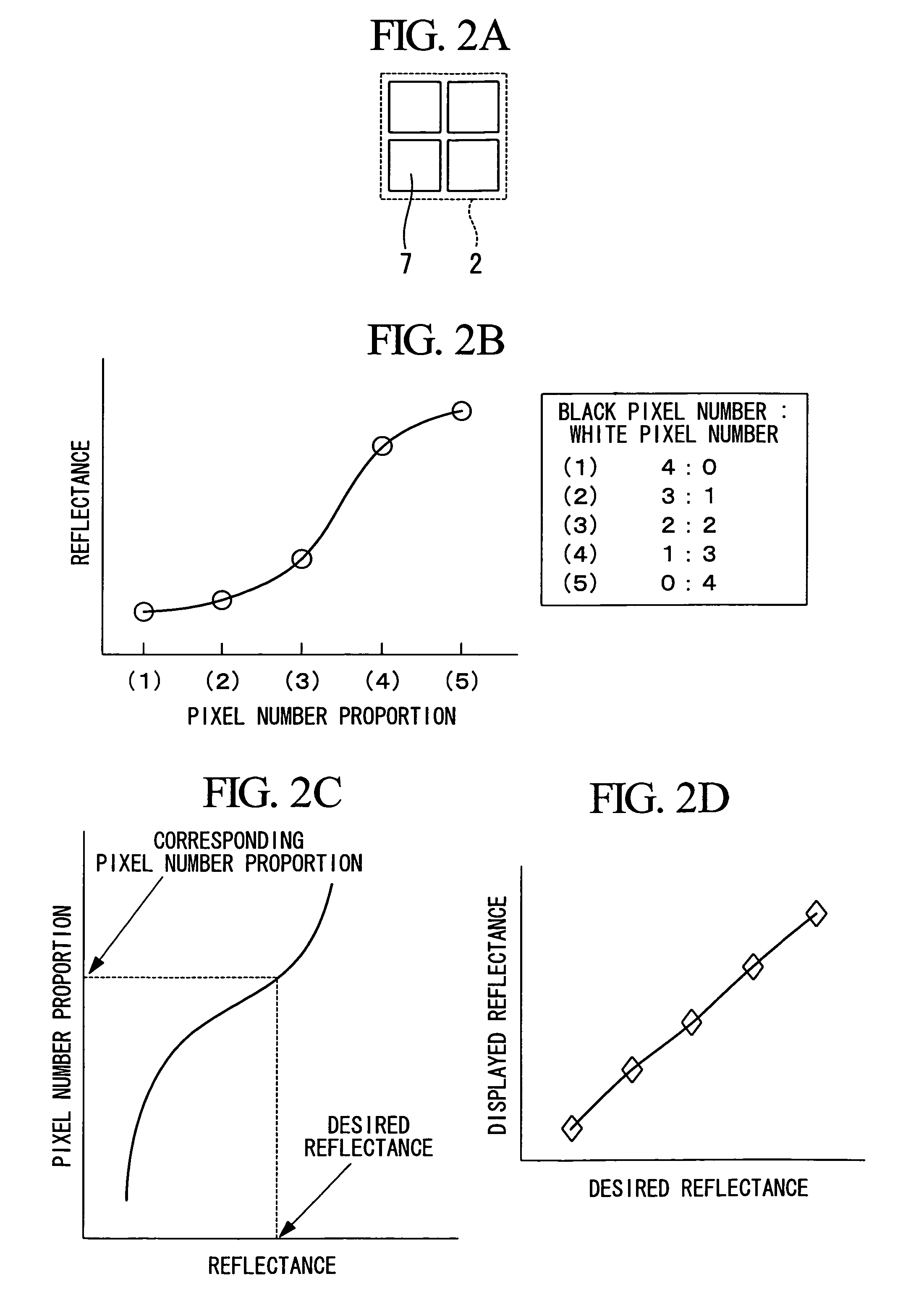
[0079]FIG. 2 shows a second embodiment of the electrophoretic device according to the present invention.

[0080]FIG. 2A shows the pixel structure. In the present electrophoretic device, the display region 2 includes four pixel electrodes 7 having two arranged horizontally and two vertically. In the description hereunder, as examples, the reflectance is used for the optical characteristic, black (that is low reflectance state) is used for a first optical characteristic, and white (that is high reflectance state) is used for a second optical characteristic. However, the examples are simply for the sake of convenience as described above.

[0081]FIG. 2B is an example of the reflectance measurement data in the case where the proportion of the black pixel number and the white pixel number is changed in the electrophoretic display device having such a pixel structure. A spectrophotometer, SpectroEye made by GretagMacbeth AG. was used for the measurement of reflectance. Although the number of t...

embodiment 3

[0084]FIG. 3 is a sectional view showing the structure a pixel portion in a third embodiment of the electrophoretic device according to the present invention.

[0085]In the present embodiment, as shown in FIG. 3, the electrophoretic particles include two different types of particles 12a and 12b. Other components are similar to those in the above-mentioned Embodiment 1.

[0086]Hereunder is a description of the operation of the electrophoretic device according to the present embodiment. In the following description, it is assumed that the electrophoretic particles 12a are white and positively charged and the electrophoretic particles 12b are black and negatively charged. However, the color of the particles and the charging polarity is not specifically limited. For example, even if the charging polarity is reversed, the direction of applying the voltage need only be reversed, and the same principal can be applied for explanation.

[0087]In FIG. 3, when the negative first voltage (for example...


PUM


Abstract

The electrophoretic device of the present invention obtains a plurality of different optical characteristics by changing a proportion of number of pixel electrodes supplied with a first voltage and a number of pixel electrodes supplied with a second voltage. The transition of the optical characteristics accompanied by the changes of the proportion is previously obtained as an actual measurement value. The preferable proportion displaying the desired optical characteristic is calculated based on the actual measurement value.

Description

BACKGROUND OF THE INVENTION[0001]1. Field of the Invention[0002]The present invention relates to an electrophoretic device, method of driving electrophoretic device, and electronic apparatus. In particular, the invention relates to an electrophoretic device that has an electrophoretic dispersion liquid including a liquid dispersion medium and electrophoretic particles, to method of driving electrophoretic device, and to electronic apparatus comprising the electrophoretic device which uses the driving method.[0003]Priority is claimed on Japanese Patent Application No. 2005-60532, filed Mar. 4, 2005, the content of which is incorporated herein by reference.[0004]2. Description of Related Art[0005]In relation to an electrophoretic device which has an electrophoretic dispersion liquid including a liquid dispersion medium and electrophoretic particles, there is heretofore known an electrophoretic display device that utilizes the fact that when an electric field is applied to the electrop...

Claims


Application Information

Patent Timeline
Patent Type & Authority Patents(United States)
IPC IPC(8): G09G3/34
CPCG09G3/344G09G3/207G09G2300/0434G09G2320/0233G09G2320/0285G09G2360/145
Inventor KAWAI, HIDEYUKI
Owner E INK CORPORATION
Why Eureka
Try Eureka