Image capturing device having pulsed LED flash

a technology of led flash and image capturing device, which is applied in the direction of exposure control, optical radiation measurement, instruments, etc., can solve the problems of insufficient luminance, inability to obtain luminance as necessary for flash use, and increase in power consumption pd by more than a factor of 2.5, so as to eliminate waste

Active Publication Date: 2014-04-01
SHARP KK
View PDF26 Cites 3 Cited by
  • Summary
  • Abstract
  • Description
  • Claims
  • Application Information

AI Technical Summary

Benefits of technology

The present invention relates to image capturing devices that use multiple light emitting diodes (LEDs) as an illumination source. By driving the LEDs in a pulsed fashion, the devices achieve higher light output and reduced heat generation. This allows for increased luminance of the LEDs, improved reliability, and reduced power consumption. The devices also allow for adjustment of color balance and exposure dose while maintaining illumination source color balance. Additionally, the devices make it possible to adjust illumination source color balance in response to changes in photographic field angle, reducing waste of light and improving image quality.

Problems solved by technology

However, when attempting to use LED(s) as flash apparatus(es) as in the aforementioned conventional art, there has been the problem that luminance has been insufficient.
That is, no matter how large LED drive current is made, LED luminance does not exceed some fixed limit; and it is consequently impossible to obtain luminance as necessary for flash use.
And yet, power consumption Pd actually increases by more than a factor of 2.5.
When used as a camera flash, because drive current Id will reach far greater value(s), at on the order of 200 mA for each LED element of each respective color, the effect of the heat generated thereby will be even more serious.
Moreover, there has also been the problem that over the course of usage the resin that encapsulates the LED element(s) can crack due to heat (cracking) and / or separation thereof from package(s) may occur.

Method used


Image

  • Image capturing device having pulsed LED flash
  • Image capturing device having pulsed LED flash
  • Image capturing device having pulsed LED flash

Examples


first embodiment

[0038]-First Embodiment-

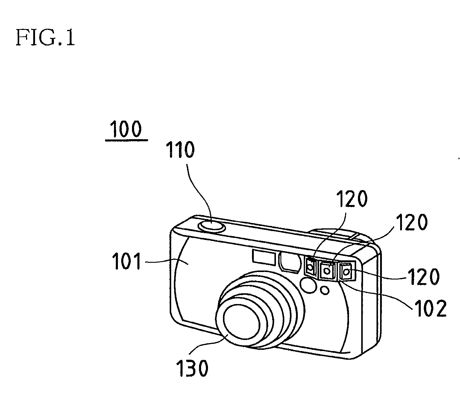
[0039]FIG. 1 is a drawing showing the external appearance of a camera associated with a first embodiment of the image capturing device of the present invention. Note that this camera is assumed to use silver halide film.

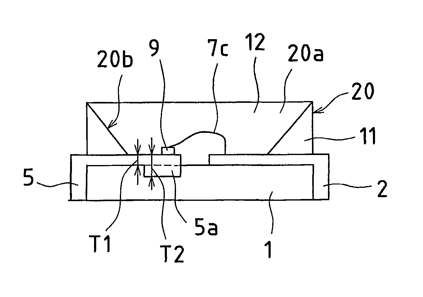
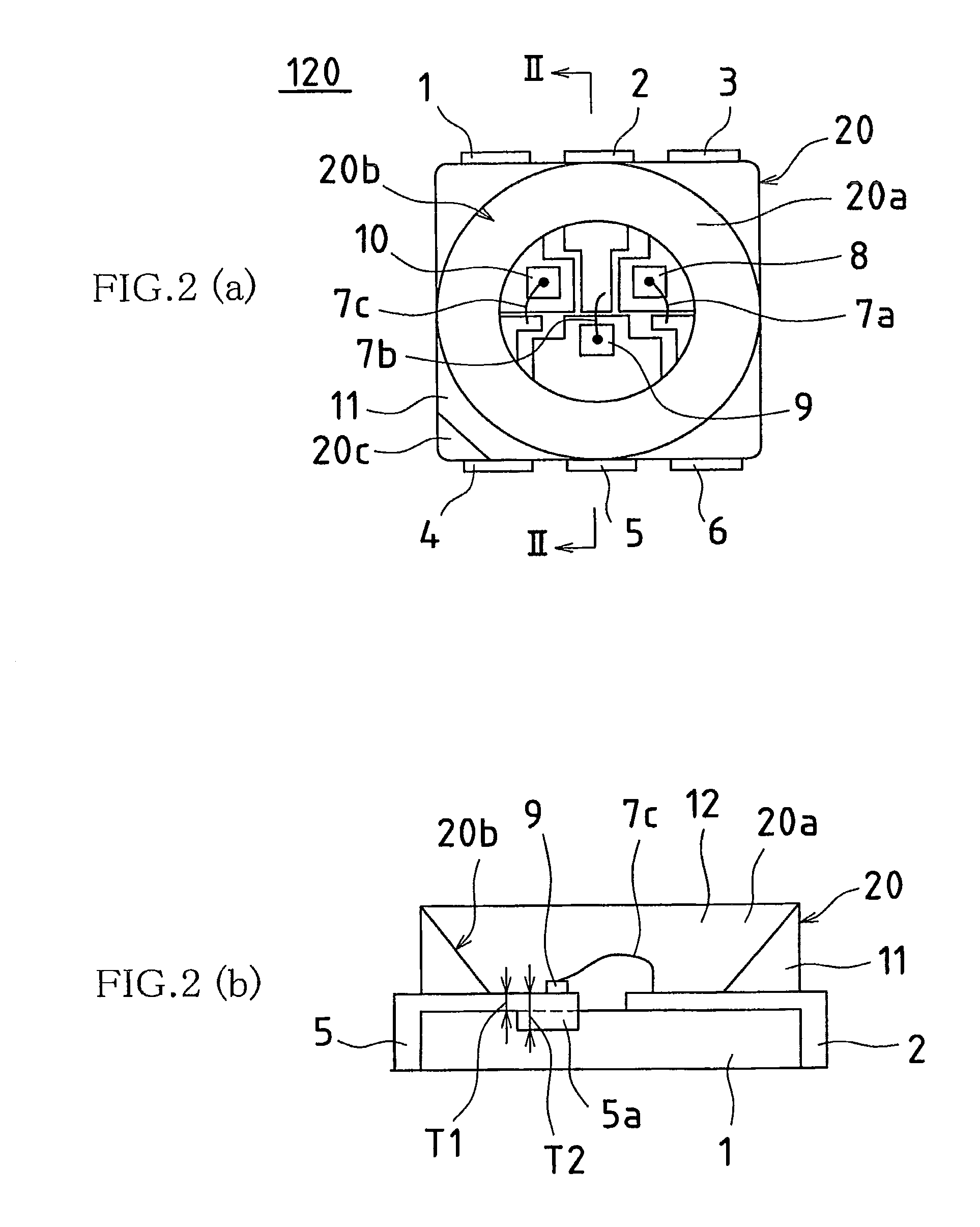
[0040]As shown in FIG. 1, photographic lens 130 equipped with multibarrel lens barrel is arranged toward the bottom in roughly the central region of the front of body 101 of squat box-shaped camera 100. This photographic lens 130 can be extended and / or retracted as a result of actuation by actuating member(s), not shown; extension and / or retraction of photographic lens 130 permitting change in photographic magnification. Three LED devices 120 for flash use are arranged at protruding region 102 formed in the upper right region at the front of camera body 101. These LED devices 120 for flash use are arranged so as to permit light to respectively be irradiated centrally within the field angle of photographic lens 130 as well as to the left and ri...

second embodiment

[0077]-Second Embodiment-

[0078]FIG. 7(a) indicates when a shutter might be open and when it might be closed in an example of a drive signal timing chart for LEDs for flash use in a camera associated with a second embodiment of the image capturing device of the present invention; and FIG. 7(b) shows the corresponding LED drive signals. Note that because, except for the features mentioned below, the second embodiment is identical to the first embodiment which was described with reference to FIGS. 1 through 6, only those aspects that are different therefrom will be described here.

[0079]Internal to this camera is / are monitoring light-receiving element(s) capable of measuring amount(s) of light impinging on image capturing element(s) after passing through photographic lens(es). In the event that LED element(s) is / are used as flash apparatus(es), it is possible, unlike the situation with conventional xenon discharge tubes, to cause light to be emitted in repeated fashion. In the present c...


PUM


Abstract

An image capturing device employing as illumination source(s) (flash apparatus(es)) a plurality of light emitting diodes emitting light of different colors; wherein such light emitting diodes are respectively made to emit light in pulsed fashion in turn by emitted color during exposure time(s). Furthermore, during exposure time(s), such light emitting diodes may be made to sequentially emit light in pulsed fashion in turn by emitted color, and / or such light emitting diodes may be made to sequentially emit light in pulsed fashion in turn by emitted color over multiple iterations.

Description

BACKGROUND OF INVENTION[0001]This application is a Continuation application of U.S. application Ser. No. 10 / 909,409 filed on Aug. 3, 2004, now abandoned which claims priority under 35 U.S.C. §119(a) to Patent Application No. 2003-286030 filed in Japan on Aug. 4, 2003, and 2004-174230 filed in Japan on Jun. 11, 2004, all of which are hereby expressly incorporated by reference into the present application.[0002]This application claims priority under 35 USC 119(a) to Patent Application No. 2004-174230 filed in Japan on 11 Jun. 2004, the content of which is incorporated herein by reference in its entirety.[0003]The present invention relates to such image capturing devices as movie-type equipment, CCD cameras, CMOS imagers, and silver halide cameras employing LED device(s) as illumination source(s); and in particular, relates to image capturing devices permitting increased effective luminance of illumination source(s) employing LED device(s).[0004]Use of R, G, and B light emitting diodes...

Claims


Application Information

Patent Timeline
Patent Type & Authority Patents(United States)
IPC IPC(8): G03B7/16H04N5/222H05B37/02G03B15/02H04N5/238H05B41/34G03B7/093G03B15/03G03B15/05H01L33/00H04N101/00G03B7/28F21V7/04H04N9/04H04N5/225
CPCH04N5/2256G03B15/05H04N2101/00H04N5/2354G03B2215/0503G03B2215/0567H01L2224/48091H01L2224/48247H01L2224/48465H04N23/56H04N23/74H01L2924/00014H01L2924/00
Inventor KAMETANI, EIJIYAMAMOTO, YOSHIHIKOCHIKUGAWA, HIROSHI
Owner SHARP KK
Why Eureka
Try Eureka