
Methods and system for operating an engine

a technology of hybrid vehicles and powertrains, applied in the direction of machines/engines, electric control, transportation and packaging, etc., can solve the problems of reducing the vacuum produced by the engine, reducing the efficiency of catalysts, and driver fatigue, so as to achieve the effect of reducing the number of exhaust gas conversions, and increasing catalyst efficiency

Inactive Publication Date: 2019-08-27
FORD GLOBAL TECH LLC
View PDF34 Cites 0 Cited by
  • Summary
  • Abstract
  • Description
  • Claims
  • Application Information

AI Technical Summary

Benefits of technology

[0002]An internal combustion engine may include a catalytic converter to process engine exhaust gases into N2, H2O and CO2. Once the catalyst has reached a catalyst light off temperature, the catalyst provides a threshold exhaust gas conversion efficiency. The catalyst light off temperature is much high than ambient temperature. Consequently, the catalyst may not convert exhaust gases efficiently as is desired after an engine has started from ambient conditions. One way to increase catalyst efficiency during engine starting is to retard spark timing from a base spark timing shortly after engine starting so that a greater percentage of heat released from combustion of air and fuel in the cylinder reaches the catalyst. Further, an amount of air inducted to engine cylinders can be increased to further increase catalyst temperature sooner after engine start. However, increasing an amount of air inducted to the engine reduces vacuum produced by the engine. As a result, the engine may be able to supply less vacuum to vacuum consumers, such as vehicle brakes, during engine starting. If a driver applies vehicle brakes after engine starting when low vacuum is present, the driver may experience hard brake pedal feel. Thus, it may be desirable to provide a way of heating a catalyst while providing vacuum to vacuum consumers during low driver demand torque conditions.
[0004]By commanding a motor to rotate an engine while the engine is combusting air and fuel at an idle speed and producing torque insufficient to rotate the engine, an increased amount of thermal energy may be provided to heat a catalyst. For example, spark timing of the engine may be retarded from minimum spark timing for best engine torque (MBT) so that the engine produces torque insufficient to rotate the engine at idle speed. The retarded spark timing delays ignition so that additional heat flows out of the engine to the catalyst. Further, the engine may be rotated via the motor to generate additional vacuum. By lowering the load on the engine via the motor, the engine may operate with less air so that the throttle may be closed further to generate additional vacuum for vacuum consumers on board the vehicle.
[0005]The present description may provide several advantages. Specifically, the approach may reduce catalyst heating time and reduce engine emissions. Further, the approach may provide increased vacuum when vacuum may be difficult to produce. Further still, the approach provides a way of heating a catalyst via the vehicle's battery without having to install an electrical heater in the vehicle's exhaust system.
[0006]For example, by motoring an engine with 2 kW of energy provided by a motor, the engine is able to produce approximately 2 kW of additional catalyst heat at the same intake manifold vacuum level if the engine provided heat to the catalyst without the motor. Or, the engine can produce a deeper vacuum at the same catalyst heating level. This approach provides a surprising serendipitous result. Specifically, since the engine is being motored primarily with an electric motor instead of combustion torques, it smoothness increased remarkably and allows even greater spark retard where without this feature, the engine would encounter a problematic combustion stability limit while spark was being retarded. Thus, rapid catalyst heating may be achieved while maintain a desired intake manifold vacuum while experiencing increased engine smoothness during catalyst heating. Further, the approach enables running the engine at very low Indicated Mean Effective Pressure (IMEP), which is known to produce low hydrocarbon emissions and is one objected for fast catalyst light-off. As such, the catalyst heating is performed while producing a fewer hydrocarbon emissions than would occur if the combustion pressures were spinning the engine.

Problems solved by technology

Consequently, the catalyst may not convert exhaust gases efficiently as is desired after an engine has started from ambient conditions.
However, increasing an amount of air inducted to the engine reduces vacuum produced by the engine.
If a driver applies vehicle brakes after engine starting when low vacuum is present, the driver may experience hard brake pedal feel.
For example, spark timing of the engine may be retarded from minimum spark timing for best engine torque (MBT) so that the engine produces torque insufficient to rotate the engine at idle speed.
Further, the approach may provide increased vacuum when vacuum may be difficult to produce.
This approach provides a surprising serendipitous result.
Specifically, since the engine is being motored primarily with an electric motor instead of combustion torques, it smoothness increased remarkably and allows even greater spark retard where without this feature, the engine would encounter a problematic combustion stability limit while spark was being retarded.
Further, the approach enables running the engine at very low Indicated Mean Effective Pressure (IMEP), which is known to produce low hydrocarbon emissions and is one objected for fast catalyst light-off.

Method used


Image

  • Methods and system for operating an engine
  • Methods and system for operating an engine
  • Methods and system for operating an engine

Examples


Embodiment Construction

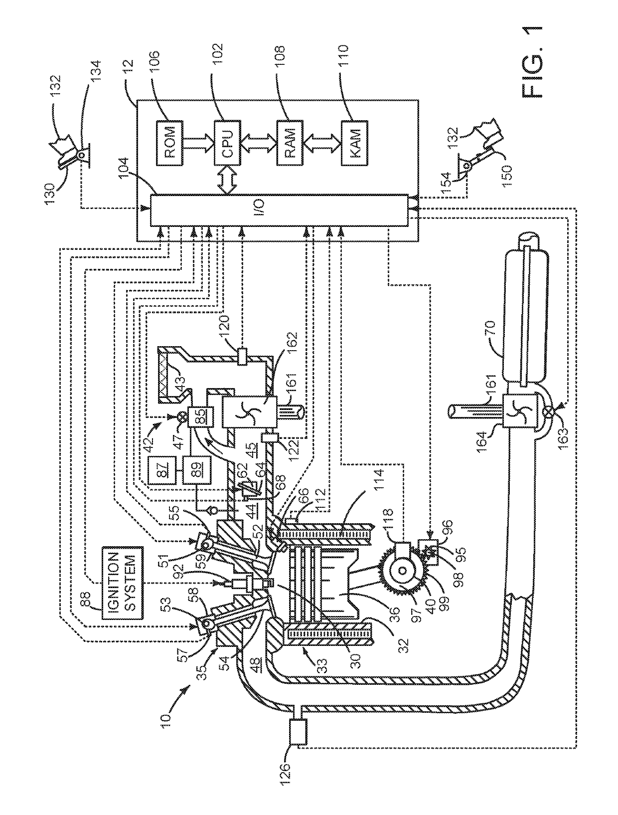
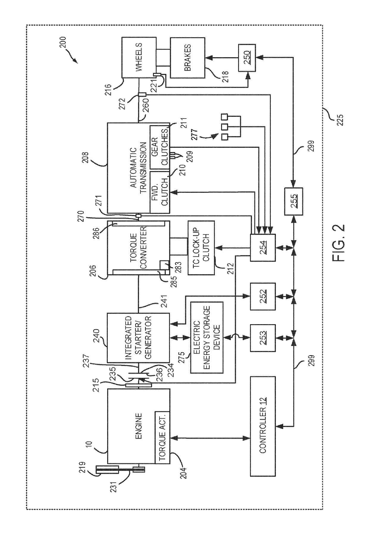
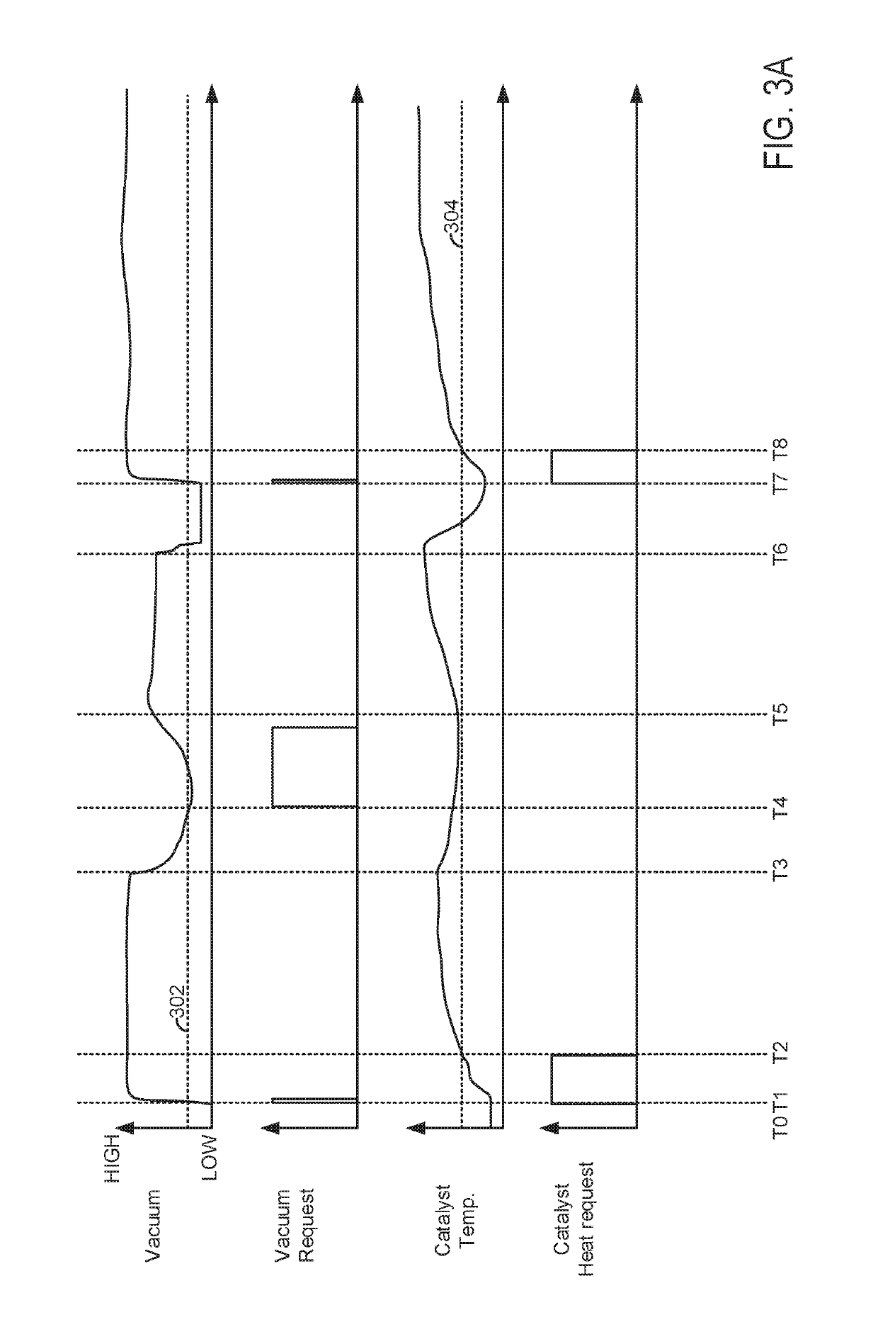
[0015]The present description is related to increasing catalyst heating and vacuum production via a motor of a hybrid vehicle. The motor may be included in a parallel or series hybrid vehicle. The hybrid vehicle may include an engine as shown in FIG. 1. The engine of FIG. 1 may be included in a driveline shown in FIG. 2. The system of FIGS. 1 and 2 may provide the operating sequence shown in FIGS. 3A and 3B. The method of FIG. 4 may be included in the system of FIGS. 1 and 2 to provide the operating sequence illustrated in FIGS. 3A and 3B.

[0016]Referring to FIG. 1, internal combustion engine 10, comprising a plurality of cylinders, one cylinder of which is shown in FIG. 1, is controlled by electronic engine controller 12. Engine 10 is comprised of cylinder head 35 and block 33, which include combustion chamber 30 and cylinder walls 32. Piston 36 is positioned therein and reciprocates via a connection to crankshaft 40. Flywheel 97 and ring gear 99 are coupled to crankshaft 40. Option...


PUM


Abstract

Systems and methods for increasing engine vacuum production and catalyst heating of a hybrid powertrain are described. In one example, a motor / generator rotates an engine at idle speed while the engine combusts air and fuel without providing torque sufficient to rotate the engine so that spark timing may be advanced or retarded from minimum spark timing for best torque to heat a catalyst and generate vacuum for vacuum consumers.

Description

FIELD[0001]The present description relates to methods and a system for operating a powertrain of a hybrid vehicle. The methods and systems may be particularly useful for hybrid vehicles that include an engine and a belt integrated starter / generator and / or a motor / generator.BACKGROUND AND SUMMARY[0002]An internal combustion engine may include a catalytic converter to process engine exhaust gases into N2, H2O and CO2. Once the catalyst has reached a catalyst light off temperature, the catalyst provides a threshold exhaust gas conversion efficiency. The catalyst light off temperature is much high than ambient temperature. Consequently, the catalyst may not convert exhaust gases efficiently as is desired after an engine has started from ambient conditions. One way to increase catalyst efficiency during engine starting is to retard spark timing from a base spark timing shortly after engine starting so that a greater percentage of heat released from combustion of air and fuel in the cylin...

Claims


Application Information

Patent Timeline
Patent Type & Authority Patents(United States)
IPC IPC(8): F02D35/00B60W20/10F01N3/20B60W10/08B60W10/06F02D35/02F02D41/00F02D41/02F02D41/08F02D37/02
CPCF02D29/02F02D37/02F02D41/0002F02D41/027F02D41/08F02P5/1502F02P5/1508F02D2250/41F02D2250/18F02D2200/502F02D2200/60F02D2200/0802F02D2200/0804F02D41/0007F02D2041/0012F02D41/0255F02D41/086B60K6/48B60K2006/4825B60W20/16B60W10/06B60W10/08Y02T10/12Y02T10/40Y02T10/62B60W20/10B60W2510/06B60W2710/0605B60W2710/0666B60W2710/083F01N3/2006F02D35/0023F02D35/023
Inventor PURSIFULL, ROSS DYKSTRACUNNINGHAM, RALPH WAYNE
Owner FORD GLOBAL TECH LLC
Learn More