Vacuum sealed package, printed circuit board having vacuum sealed package, electronic device, and method for manufacturing vacuum sealed package

一种真空密封封装、制造方法的技术,应用在仪器、电路、科学仪器等方向,能够解决无法再吸附气体等问题,达到防止真空度的下降、提高生产率、降低制造成本的效果

Inactive Publication Date: 2012-01-11
NEC CORP
View PDF9 Cites 15 Cited by
  • Summary
  • Abstract
  • Description
  • Claims
  • Application Information

AI Technical Summary

Problems solved by technology

[0008] As a getter material, for example, zirconium, vanadium, iron, or alloys of these are used, but if left in the atmosphere, gas molecules are adsorbed to the surface, and the state becomes saturated where no more gas can be adsorbed

Method used


Image

  • Vacuum sealed package, printed circuit board having vacuum sealed package, electronic device, and method for manufacturing vacuum sealed package
  • Vacuum sealed package, printed circuit board having vacuum sealed package, electronic device, and method for manufacturing vacuum sealed package
  • Vacuum sealed package, printed circuit board having vacuum sealed package, electronic device, and method for manufacturing vacuum sealed package

Examples


Embodiment 2

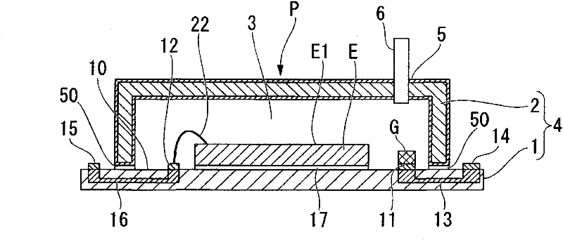
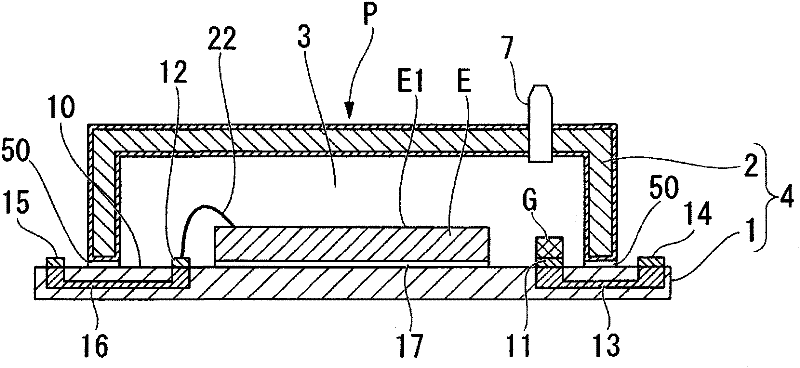
[0186] Next, refer to Figure 15 to Figure 25 Example 2 of the present invention will be described. exist Figure 15 as well as Figure 16 in, for with Figure 1 to Figure 14 The same reference numerals are assigned to the same parts as the described structural elements, and description thereof will be omitted. This second embodiment has the same structure as the above-mentioned first embodiment, so the difference will be mainly described. also, Figure 15 is a cross-sectional view showing the state before the through-hole 5 is sealed, Figure 16 It is a cross-sectional view showing the through-hole 5 after sealing.

[0187] In the second embodiment, the through-hole 5 for evacuation is formed in advance in the second main body 2 serving as the lid member of the main body 4 which is hermetically sealed. The method of sealing the through hole 5 is different from that of the first embodiment. The number of through-holes 5 may be one, but it is preferable to form a plural...

Embodiment 3

[0231] Next, refer to Figure 26A to Figure 28 The above-mentioned Embodiment 3 will be described. In these figures, for the previous Figure 1 to Figure 25 The same reference numerals are assigned to the same parts as the described constituent elements, and description thereof will be omitted. Next, points different from the above-described embodiment will be described. In addition, Example 3's Figure 26A It is an example in which the first conductor pad 11 and the second conductor pad 12 are provided at opposing positions across the electronic device E, Figure 26B This is an example in which the first conductive pad 11 and the second conductive pad 12 are provided at adjacent positions on the sides of the electronic device E.

[0232] The width 51 of the conductor pad 50 surrounding the electronic device E formed on the wiring board 10 , which is a feature of Embodiment 3 of the present invention, will be described.

[0233] As shown in Embodiments 1 and 2 of the pres...

Embodiment 4

[0239] Next, refer to Figure 29 to Figure 31 Embodiment 4 of the present invention will be described. In these Figure 29 to Figure 31 in, for with Figure 1 to Figure 28 Where the components described are equivalent, the same reference numerals are attached, and description thereof will be omitted. Next, points different from the above-described embodiment will be described.

[0240] The through-hole 5 in Embodiment 4 is formed in a tapered shape in which the diameter of the hole gradually decreases from the outermost surface of one side surface of the second body portion 2 or the wiring board 10 toward the opposite side surface.

[0241] In this way, if the diameter of the through-hole 5 is formed into a tapered shape in which the diameter of the hole gradually becomes smaller from the outermost surface of one side surface of the second main body 2 or the wiring board 10 toward the opposite side surface, not only the second The inner surface of the through-hole 5 can al...


PUM


Abstract

Disclosed is a vacuum sealed package which comprises a package main body in which a first main body part and a second main body part are joined together with a hollow part interposed therebetween, and a getter material and an electronic device which are provided within the hollow part. The vacuum sealed package is obtained by sealing the package main body with a sealing member, while maintaining the hollow part in an evacuated state by means of a through hole by which the inside and the outside of the hollow part are communicated with each other. The getter material and the electronic device are connected with a first conductor pad and a second conductor pad. The first conductor pad is connected with a third conductor pad through a heat conducting material, and the second conductor pad is electrically connected to a fourth conductor pad that is on a wiring substrate.

Description

technical field [0001] The present invention relates to a vacuum-sealed package for vacuum-sealing electronic devices and a manufacturing method thereof. Background technique [0002] Recently, miniaturization, high performance, and low cost are required in packages or devices in which electronic devices such as infrared sensors, gyro sensors (angular velocity sensors), temperature sensors, pressure sensors, and acceleration sensors are vacuum-sealed. Among them, packages or devices equipped with infrared sensors (infrared light-receiving elements) such as security surveillance cameras used at night and thermal infrared imagers (thermography) that calculate and display temperature distribution, require high vacuum sealing inside. [0003] Generally, there are quantum type and thermal type as infrared light receiving elements. Among them, although the thermal type has poor tracking performance compared with the quantum type, the thermal type is a method of detecting relative...

Claims


Application Information

Patent Timeline
Patent Type & Authority Applications(China)
IPC IPC(8): H01L23/02G01J1/02H01L23/26
CPCH01L2924/3025G01J5/045H01L2924/01079H01L2224/32225H01L2924/10253H01L2224/48227H01L2224/73265H05K5/066H01L2924/15192H01L23/10H01L23/26G01J5/029H01L2224/48091H01L2924/09701H01L2924/19107H01L23/057H01L24/73H01L2924/14H01L2924/16151H01L2924/16152G01J5/051H01L2924/00012H01L2924/00014H01L2924/00
Inventor 山崎隆雄佐野雅彦仓科晴次
Owner NEC CORP
Why Eureka
Try Eureka