Vacuum valve with vacuum gauge function

A vacuum valve and vacuum gauge technology, which is applied to packaging, kitchen utensils, household utensils and other directions under vacuum/special atmosphere, can solve the problems of rising manufacturing cost, increased assembly time, and increased number of parts, and achieves the effect of simple structure

Inactive Publication Date: 2003-07-16
KOREA ALPHALINE CO LTD
View PDF0 Cites 12 Cited by
  • Summary
  • Abstract
  • Description
  • Claims
  • Application Information

AI Technical Summary

Problems solved by technology

However, providing a vacuum valve and a separate vacuum gauge has problems such as an increase in the number of parts, an increase in assembly time due to assembly man-hours, and an increase in manufacturing cost.
In particular, the vacuum valve and vacuum gauge are only separated by a predetermined distance, and the vacuum state cannot be easily recognized
For example, after storing food in the container body, although the inside of the container body cannot maintain a vacuum state, there will be problems such as storing the container in this state.

Method used


Image

  • Vacuum valve with vacuum gauge function
  • Vacuum valve with vacuum gauge function
  • Vacuum valve with vacuum gauge function

Examples


Embodiment 1

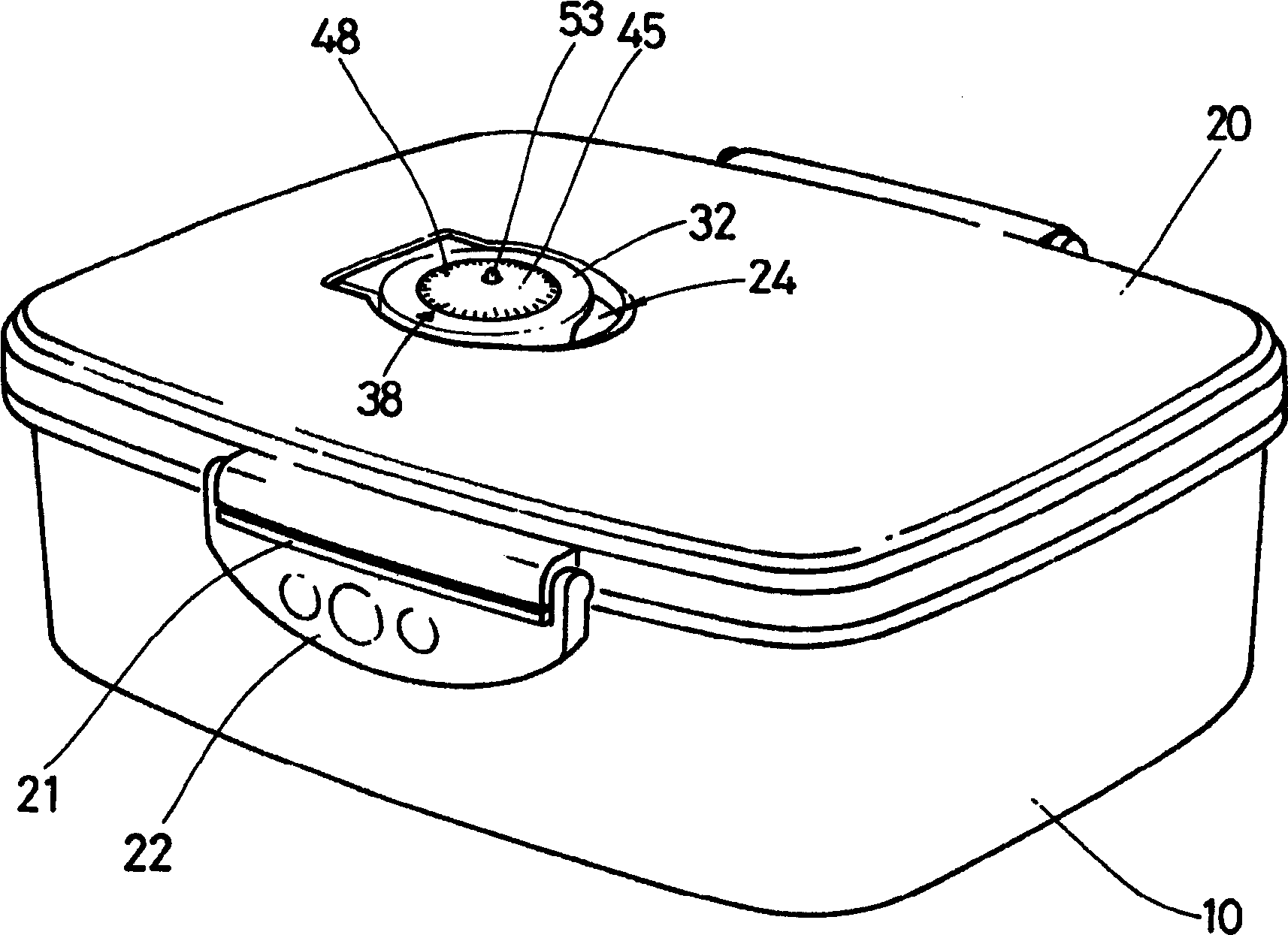
[0027] First, refer to figure 1 The structure of the vacuum storage container equipped with the vacuum valve of this embodiment is demonstrated. and figure 1 It is a perspective view of the vacuum storage container provided with the vacuum valve of the first embodiment of this embodiment.

[0028] First, if figure 1 Shown, the container body (10) that accommodates ordered food has an opening, and the vacuum valve of the present embodiment form is located on the container cover (20) of the input opening of the opening and closing container body (10).

[0029] The container body (10) is generally in the shape of a cuboid, and is used for storing various foods such as meat and vegetables in a vacuum state, and can maintain the freshness and preservation state of the various foods accommodated for a long time. In addition, although in this embodiment form, the container body (10) that is generally rectangular is used as an example for illustration, but as the type and shape ...

Embodiment 2

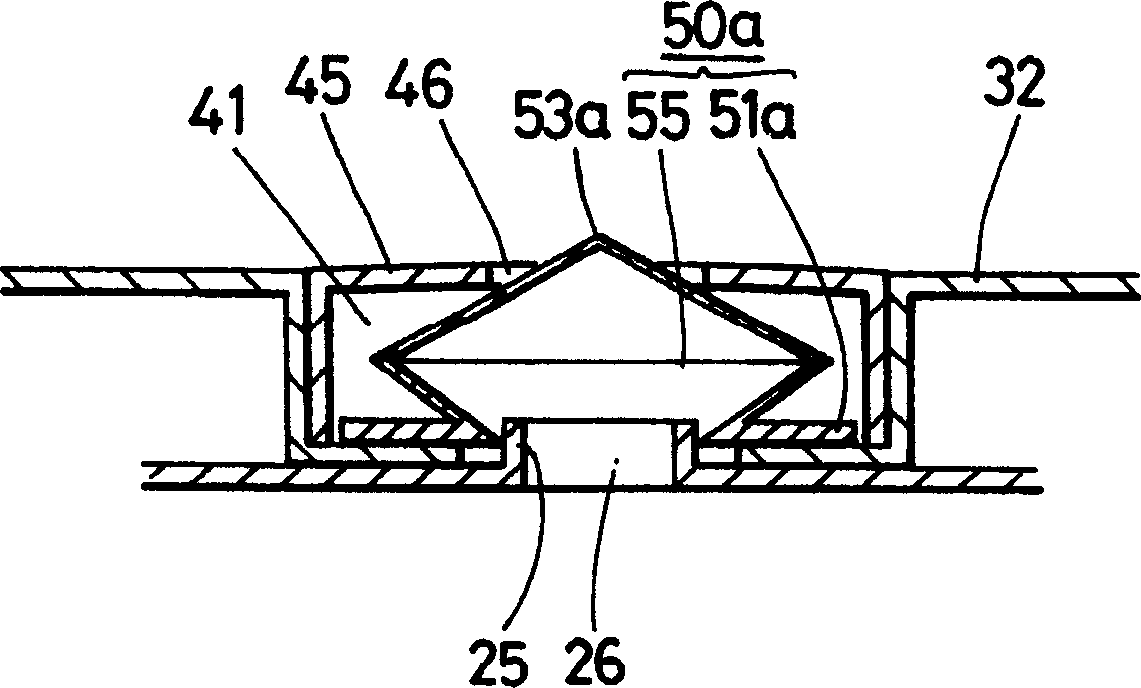
[0043] Below, refer to image 3 The structure of the vacuum valve according to the second embodiment will be described. image 3 It is a sectional view showing the structure of the vacuum valve according to the second embodiment.

[0044] First, if image 3 As shown, the vacuum holding member (50a) of this embodiment form is different from the form of the first embodiment in that it has a sealing flange portion (51a) larger than the opening diameter of the raised portion (25), and a folded portion ( 55). With this vacuum holding member (50a), the air communication port (26) can be brought into contact with the periphery of the formed protrusion (25) to keep hermetically sealed.

[0045] The vacuum holding member (50a) expands in diameter at a set height from the inside of the sealing flange portion (51a), has an upward folded portion (55), and then shrinks in diameter toward the center to form a cone. The tip (53a) of the cone moves up and down from the through hole (46) o...

Embodiment 3

[0048] Below, refer to Figure 4 The structure of the vacuum valve according to the third embodiment will be described. Figure 4 It is a sectional view showing the structure of the vacuum valve according to the third embodiment.

[0049] In this embodiment, the upper part of the protruding portion (25) is detachably connected to the hollow sealing member (30). The sealing member (30) can be formed of, for example, elastic soft silicone resin for blocking air. The sealing member (30) can simultaneously maintain the vacuum inside the vacuum holding member (50b) and the container body (10) when the rotating cover (32) described later is actuated by being embedded in the upper portion of the protrusion (25).

[0050] Sealing parts (30), such as Figure 5 As shown, it has a hollow housing part (35), and film-like protruding flange parts (31, 33) protruding radially from the upper and lower ends of the housing part (35). Hereinafter, for convenience of explanation, the protrudi...


PUM


Abstract

Disclosed is a vacuum valve including a lid (20), a depression (24) defined on the lid, a boss (25) formed on the lid at a bottom of the depression, a rotary cover (32) rotatably arranged in the depression, and a closure member detachably coupled to the rotary cover. The vacuum valve comprises a through-hole (26) defined at a center portion of the closure member; a vacuum maintaining member (50) accommodated in the closure member and having an airtightening flange part and a semi-spherical head part, the airtightening flange (51) part being brought into close contact with a portion of the rotary cover, and the semi-spherical head part projecting upward from the airtightening flange part in a rounded manner such that, as the lid of a vacuum container is repeatedly pressed and released, air existing in a container body is discharged to the outside and vacuumization is effected in the vacuum container; and an exposure bar extending upward from the semi-spherical head part by a predetermined length such that the exposure bar can be moved upward and downward through the through-hole of the closure member depending upon a vacuumization degree to allow a user to confirm a vacuumized state of the vacuum container with the naked eye.

Description

technical field [0001] The present invention relates to a vacuum valve with the function of a vacuum gauge, in particular to a vacuum valve for a container cover pressing type vacuum storage container which can make the inside of the container body into a vacuum state by pressing the container cover. Background technique [0002] Generally, a vacuum storage container has an air communication port formed in the container lid by a vacuum valve to manage the air inside the container body so that the food stored in the container body does not deteriorate and can be stored for a long time, and a vacuum valve that can control its opening and closing. As a vacuum storage container provided with the vacuum valve, a vacuum pump is used, and the container body is vacuumed by pressing the container lid with the palm of the hand. [0003] The vacuum valve provided on the container cover of the existing vacuum storage container has the following problem, because the protrusion formed on ...

Claims


Application Information

Patent Timeline
Patent Type & Authority Applications(China)
IPC IPC(8): A45C11/20A47J47/10B65D51/16B65D79/02B65D81/20
CPCY10S99/14A45C11/20A47J47/10B65D81/2038B65D79/02
Inventor 王洙昌
Owner KOREA ALPHALINE CO LTD
Why Eureka
Try Eureka