Gas shielded arc welding device

A technology of gas protection and arc welding, applied in arc welding equipment, welding equipment, manufacturing tools, etc., to achieve the effect of quality assurance

Inactive Publication Date: 2015-08-26
KOBE STEEL LTD
View PDF6 Cites 0 Cited by
  • Summary
  • Abstract
  • Description
  • Claims
  • Application Information

AI Technical Summary

Problems solved by technology

[0012] However, the ratio of semi-automatic welding methods performed manually is still high, and a method that can be easily managed is still desired from the manager's point of view

Method used


Image

  • Gas shielded arc welding device
  • Gas shielded arc welding device
  • Gas shielded arc welding device

Examples


Embodiment Construction

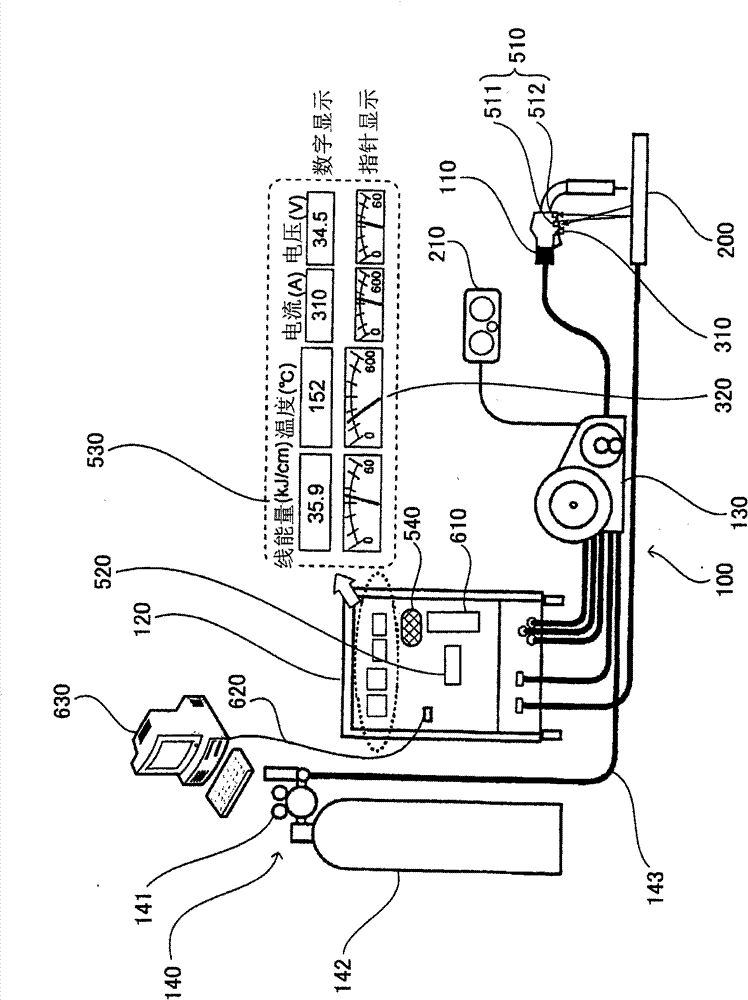
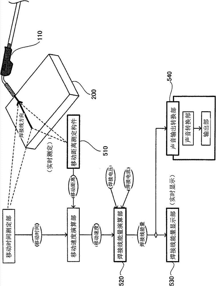
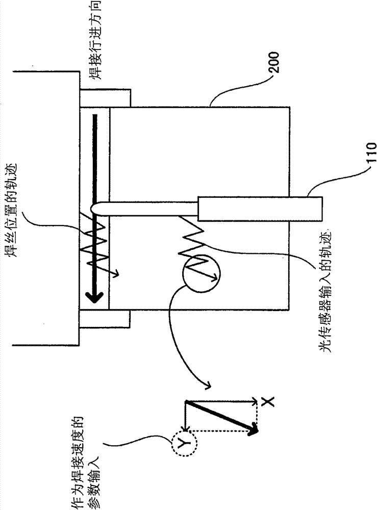
[0023] The gas shielded arc welding device 100 of the present embodiment, such as figure 1 As shown, it has: welding torch 110; welding power supply 120; welding wire supply part 130; shielding gas supply part 140; moving distance measuring member 510; welding heat energy calculation part 520; welding heat energy display part 530; sound output conversion part 540.

[0024] The welding power source 120 supplies electric power between the welding torch 110 and the steel plate 200 as a part to be welded. The welding wire supply unit 130 continuously supplies welding wire to the welding torch 110 . The supply amount of welding wire is adjusted from the outside by the remote control device 210 .

[0025] The shielding gas supply unit 140 is composed of: a tank body 142 ; a gas flow regulating valve 141 ; and a gas pipe 143 , and supplies the shielding gas jetted from the welding torch 110 . Protective gas such as CO 2 monomer gas or CO 2 Mixed gas with Ar gas.

[0026] The mov...


PUM


Abstract

A gas-shielded arc welding apparatus generates electric arc between the welding wire loaded from the welding torch and the welded object, and performs gas-shielded arc welding to the welded object. A moving distance measuring member is provided on the welding torch, for measuring the moving distance of the welding torch in the weld line direction. A weld line energy calculation part calculates the traveling speed based on the moving distance and calculates the weld line energy at every moment based on the traveling speed combined with the welding voltage and the welding current. A weld line energy display part displays the calculated weld line energy at every moment. Therefore, the manager can appropriately monitor whether the welding management standard is complied.

Description

technical field [0001] The present invention relates to a gas shielded arc welding device for generating an arc between a welding wire sent from a welding torch and an object to be welded, and more particularly to a gas shielded arc welding device for real-time display of welding energy and the like. Background technique [0002] In the field of construction, especially after the Great Hanshin-Awaji Earthquake, various technical countermeasures have been studied and put into practical use in order to improve and ensure the earthquake resistance of buildings. On the other hand, as a result of excessive efforts to ensure cost competitiveness, problems such as camouflage and falsification have occurred. Such a problem is no exception in the arc welding process when manufacturing steel bars. [0003] In order to ensure the mechanical performance of the welded part, not only the chemical composition of the steel material and the welding material, but also the management of the w...

Claims


Application Information

Patent Timeline
Patent Type & Authority Patents(China)
IPC IPC(8): B23K9/16
Inventor 铃木励一
Owner KOBE STEEL LTD
Why Eureka
Try Eureka