IP packet relay method and gateway device in communication network

A communication network and gateway technology, applied in the direction of network connection, data exchange network, data exchange through path configuration, etc., can solve the problem of no call control/call management

Inactive Publication Date: 2007-11-21
MITSUBISHI ELECTRIC CORP
View PDF1 Cites 4 Cited by
  • Summary
  • Abstract
  • Description
  • Claims
  • Application Information

AI Technical Summary

Problems solved by technology

[0023] In addition, in the current Internet connection service, many access routers are used to connect existing IP networks (LAN and WAN), so it can be considered the same as above, but the IP network on the WAN side is just "existing ” IP network without call control / call management

Method used


Image

  • IP packet relay method and gateway device in communication network
  • IP packet relay method and gateway device in communication network
  • IP packet relay method and gateway device in communication network

Examples


Embodiment 1

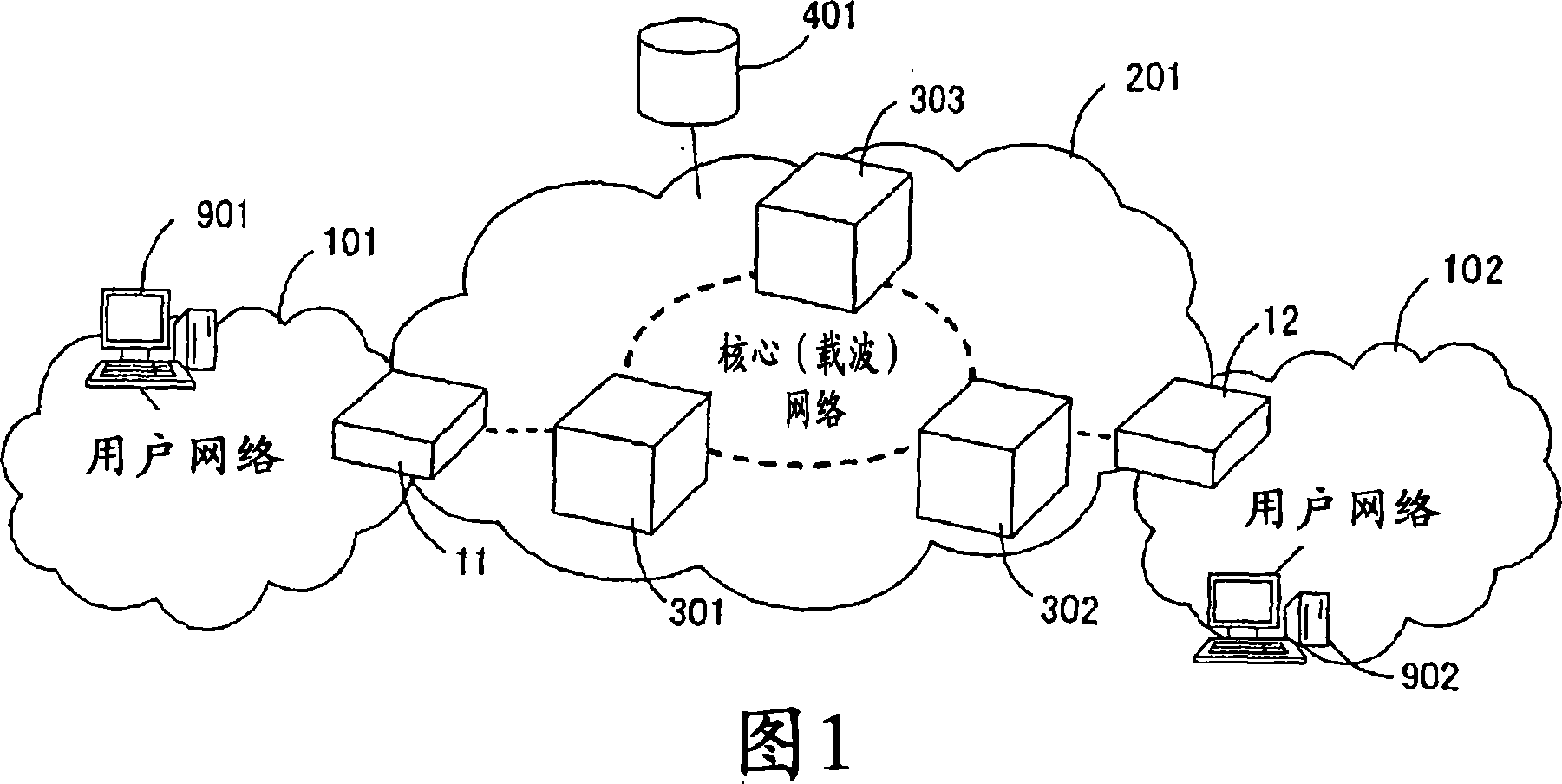
[0042] In Embodiment 1, SIP (Session Initiation Protocol), which is highly likely to be widely used as a call control protocol of an IP network in the future, will be described as an example. FIG. 1 shows the basic network structure to which Embodiment 1 is applied. In the network configuration of FIG. 1 , gateway devices (hereinafter referred to as GW devices) 11 and 12 on which the functions of the present invention are installed are realized by IP routers. Of course, this GW device may also be constituted by bridges of layer 2.

[0043] In FIG. 1, subscriber networks 101, 102 are existing IP networks without call control. The core network 201 is a network accompanying call control / call management, and includes core network nodes 301 , 302 , and 303 . The SIP server 401 is connected to the core network 201 and has a SIP proxy server installed as a basic function. 901 and 902 are existing IP terminals or servers located on the user network 101, which can serve as clients a...

Embodiment 2

[0073] Next, Embodiment 2 of the present invention will be described with reference to FIG. 5 . In this second embodiment, the GW devices 11 and 12 transfer all the TCP packets as they are, and the GW device 11 on the ingress side acquires the TCP-SYN-ACK packet from the GW device 12. After synchronization with the SIP 200 OK message, the TCP-SYN-ACK packet is transferred to the IP terminal 901 .

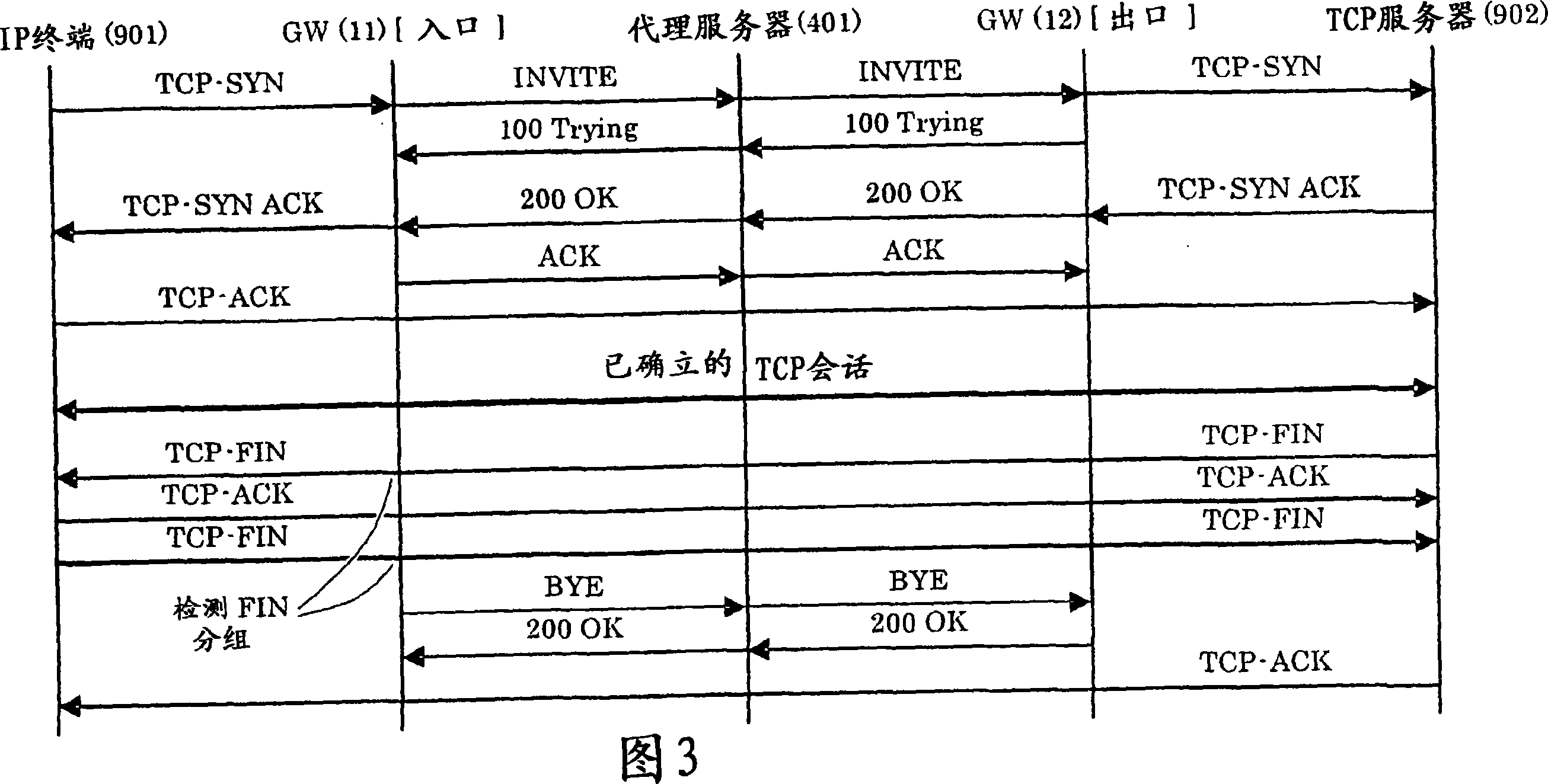
[0074] When the IP terminal 901 issues a TCP-SYN packet as a TCP session establishment request, the GW device 11 acquires the TCP-SYN packet. Then, the GW device 11 transfers the TCP-SYN packet as it is. At the same time, the GW device 12 generates a SIP INVITE packet as a call connection request packet, and transfers the generated SIP INVITE packet (INVITE message) to the SIP proxy server 401 . Upon receiving the INVITE message from the GW device 11, the SIP proxy server 401 transfers the INVITE message to the GW device 12 corresponding to the destination IP terminal. At this ti...

Embodiment 3

[0080] Next, Embodiment 3 of the present invention will be described with reference to FIG. 6 . In this third embodiment, an implementation example of accommodating UDP communication will be described. FIG. 6 shows a sequence of messages related to each constituent element of the network when a UDP session is executed in the configuration shown in FIG. 1 .

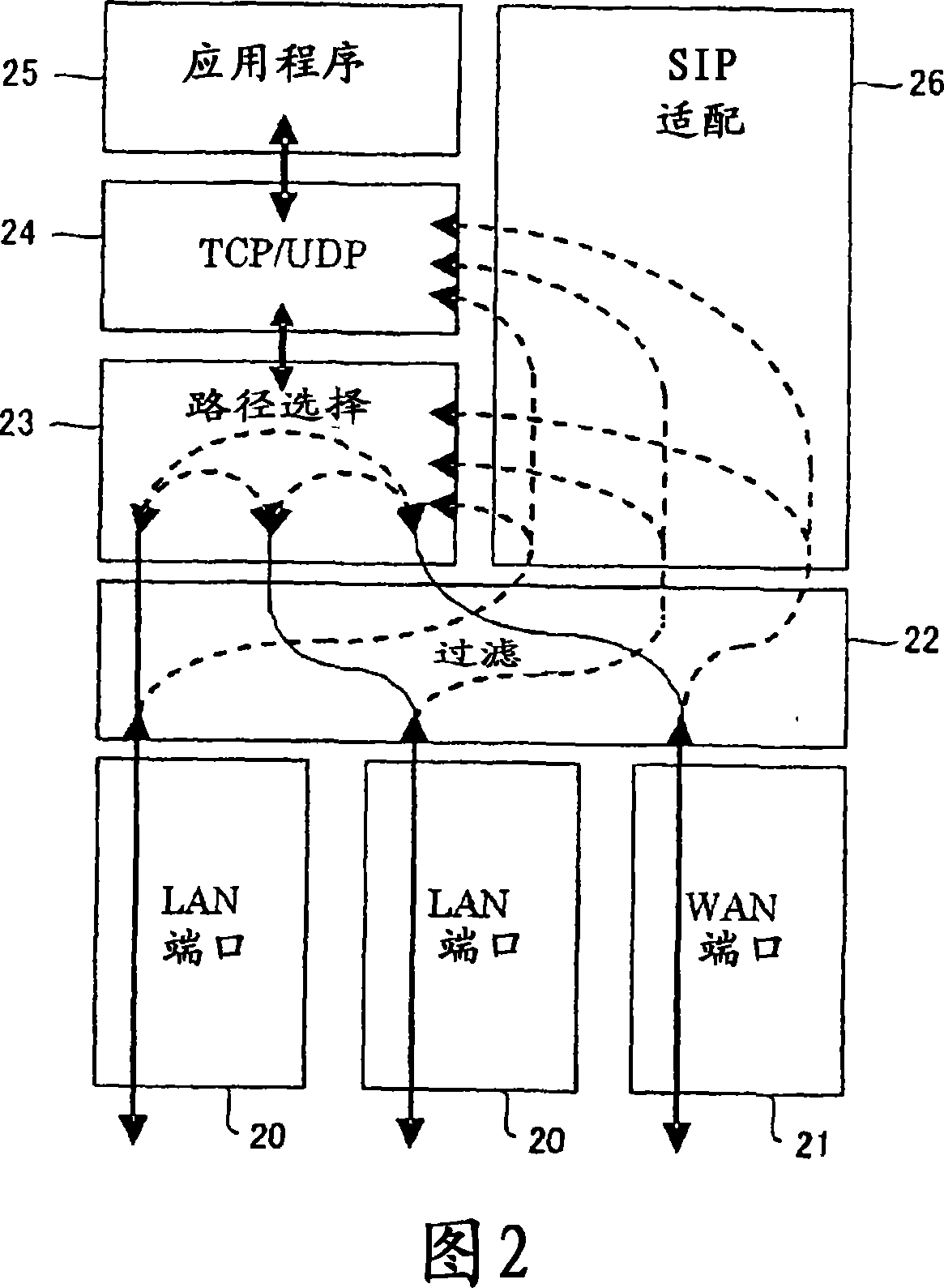
[0081] First, the filtering function unit 22 of the GW device 11 detects the first UDP packet transmitted from the IP terminal 901 . Simultaneously with this detection, the filtering function 22 forwards the UDP packet copy to the routing function 23 and the SIP adaptation function 26 of FIG. 2 . The packet transferred to the routing function unit 23 is transferred to the WAN via the WAN port 21 as it is. The packet forwarded to the SIP adaptation function 26 is used to extract the session information used to generate the INVITE message. The generated INVITE message is sent to the GW device 12 via the SIP proxy server 4...


PUM


Abstract

A plurality of user networks (101, 102) without having a call control function, which accommodates IP terminals, a core network (a call control network) (201) positioned among the user networks and having a call control and call management function, and gateways (11, 12) that connect the user networks to the core network are provided. The gateway (11, 12) captures a communication request packet issued by the user network (101, 102) or an initially transmitted data packet to analyze this, thereby establishing a necessary call in the core network (201) to allow an IP packet to pass through the core network (201). Accordingly, existing IP communication can be efficiently applied to the call control network, and the call control network as a call control target can be reliably managed.

Description

technical field [0001] The present invention relates to an IP packet relay method and a gateway device for a communication network including an IP (Internet Protocol) network, a call control network based thereon, and a gateway device for connecting them. Background technique [0002] There are various definitions of a function or a device in a position called a gateway. First, an ATM communication device such as an ATM (Asynchronous Transfer Mode) router capable of accommodating Ethernet (registered trademark) or an ATM-LAN switch is exemplified as a device in the same position as a gateway. In addition, there is also MGCP (Media Gateway Control Protocol: MGCP), which is mostly applicable to connecting existing analog telephones, PSTN (Public Switched Telephone Network: Public Switched Telephone Network), or PBX (Private Branch Exchange) to IP networks. IETF RFC3435) gateway, SIP (Session Initiation Protocol: IETF RFC3261) gateway, etc. Furthermore, H.323 (ITU-T recommend...

Claims


Application Information

Patent Timeline
Patent Type & Authority Applications(China)
IPC IPC(8): H04L12/56H04L12/66
CPCH04L65/103H04L12/2854H04L65/104H04L12/66H04L65/1069H04L29/06027H04L65/1101
Inventor 古谷信司横谷哲也佐藤浩司鹿岛和幸
Owner MITSUBISHI ELECTRIC CORP
Why Eureka
Try Eureka