
Vacuum flour mixer

A dough mixer and vacuum technology, applied in the direction of mixing/kneading with vertical installation tools, can solve problems such as product quality decline, vacuum tube blockage, affecting the effect of vacuuming, etc., and achieve the effect of solving air leakage

Inactive Publication Date: 2010-02-17
JIANGSU YINGYANG INDAL
View PDF1 Cites 12 Cited by
  • Summary
  • Abstract
  • Description
  • Claims
  • Application Information

AI Technical Summary

Problems solved by technology

The above-mentioned technical scheme has realized the continuity and vacuum of the kneading surface to a large extent, but it has the following defects. 1) The noodle delivery device fails to provide a solution to the problem of air leakage in the kneading noodle container during the feeding process. The problem that the degree of vacuum is affected, specifically, how to solve the problem of sealing during the feeding process is not given; 2) Only one stirring is performed during the dough mixing process, which may cause excessive kneading during the stirring process. Pinch the phenomenon of excessive ripening, cause the decline of product quality; 3) although have provided the vacuum pumping device, the scheme vacuum pumping device that provides in the embodiment is made up of vacuum pump and vacuum tube, but in the process of vacuum pumping, often can put Some loose noodle pieces are also sucked into the vacuum pipeline together, causing the blockage of the vacuum tube and affecting the effect of vacuuming; 4) Since various pasta have different requirements for stirring speed and stirring intensity, this requires the influence of one of the above factors. The stirring angle of the stirring paddle can preferably be adjusted, but the above-mentioned technical scheme fails to explain this

Method used


Image

  • Vacuum flour mixer
  • Vacuum flour mixer
  • Vacuum flour mixer

Examples


Embodiment Construction

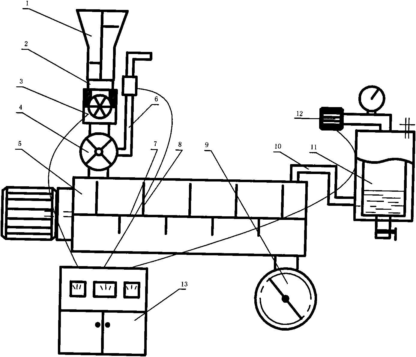
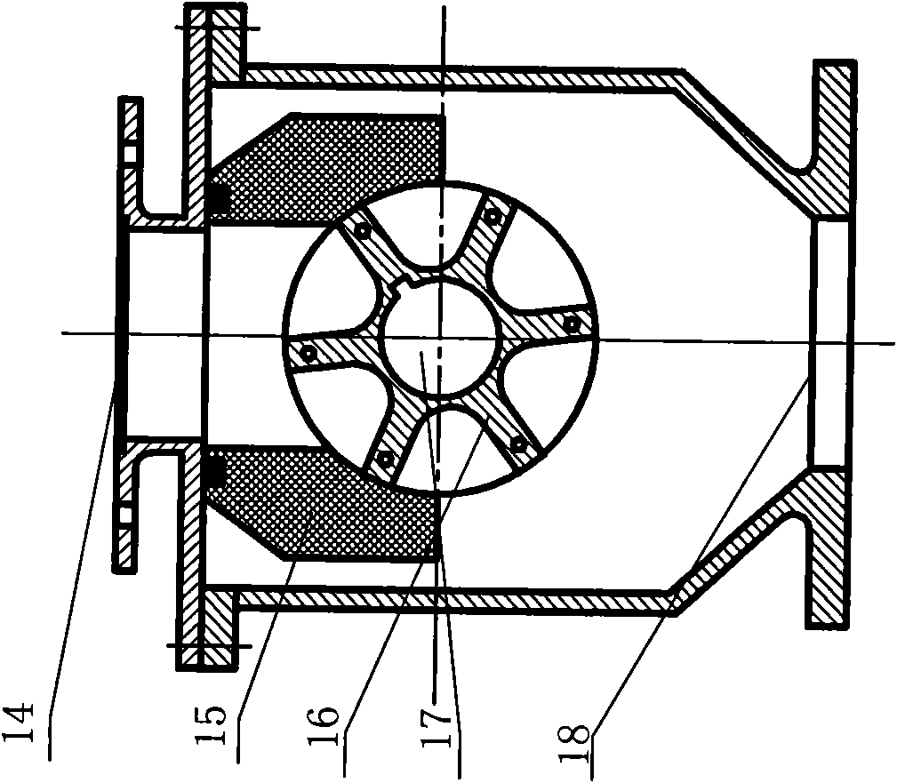
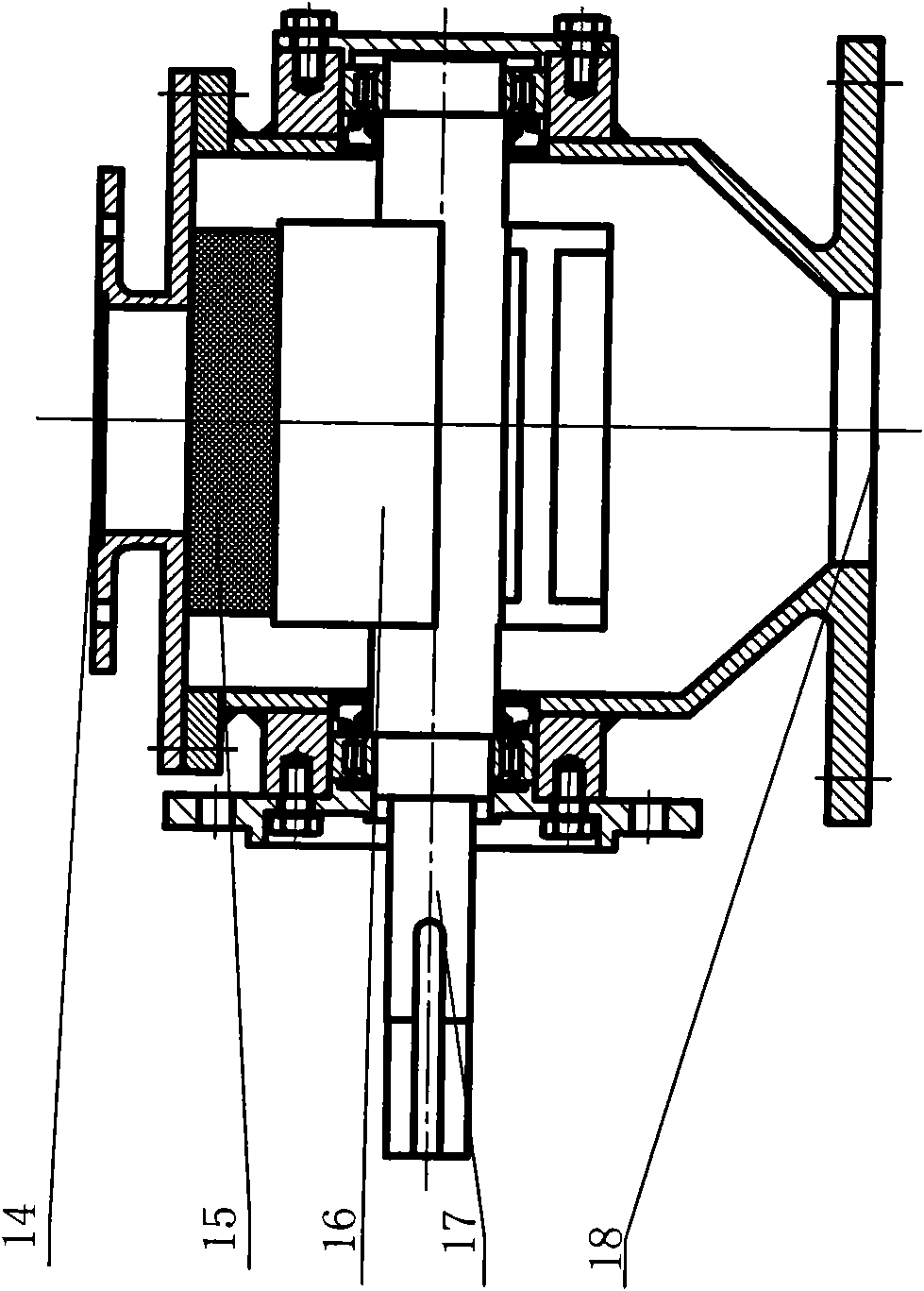
[0023] The flour of the present invention is fed through the powder feeding device 1 and supplied with water by the water feeding device 6 . The powder feeding device 1 and the water feeding device 6 are arranged on the frame, communicated with the stirring container, both of which are connected with a control device 13, and the control device 13 controls the amount of powder feeding and water feeding according to actual needs, so as to produce different products , there is a buffer plate inside the powder feeding device 1, so that the powder can be fed more smoothly. The lower part of the powder feeding device 1 is provided with a visible feeding tube 2 made of glass, which can be seen through the screw thread Connected to the powder feeding device 1, the feeding situation of the fabric can be clearly observed. In case of feeding blockage, the fault can be cleared in time. A rotary feeder connected to the stirring container is installed directly below the powder feeding device...


PUM


Abstract

The invention provides a vacuum flour mixer and relates to a continuous vacuum flour mixer, which comprises a machine frame, a driving motor and a stirring container, wherein the stirring container isarranged on the machine frame and driven by the driving motor, and the inside of the stirring container is provided with a stirrer consisting of a stirring shaft and a stirring paddle. The vacuum flour mixer also comprises a flour feeding device, a water feeding device and a discharging device which are communicated with the stirring container. The vacuum flour mixer is provided with a control device controlling the flour feeding device and the water feeding device. The vacuum flour mixer also comprises a continuous vacuumizing device which is controlled by a circuit and connected with the stirring container, wherein the vacuumizing device comprises a vacuum connecting pipe and a vacuum pump. The vacuum flour mixer is characterized in that: a rotary feeder is arranged between the flour feeding device and the stirring container; the vacuum connecting pipe is provided with a dust filtering device; and the stirring paddle is connected to the stirring shaft through an angle adjusting device. The vacuum flour mixer has the function of insulating pressure to make the inside of the stirring container keep certain vacuum degree all the time so as to ensure the flour mixing quality.

Description

technical field [0001] The invention relates to a continuous vacuum dough kneading machine, which belongs to the technical field of food production machinery. Background technique [0002] Vacuum dough mixer is an important production machine for producing instant noodles, dried noodles, macaroni, spaghetti, dumplings and other pasta. The traditional dough mixer is carried out under normal pressure. At this time, there are air bubbles in the flour in the dough container, and water Mixing makes it impossible to fully mix with water, resulting in a loose gluten network structure in the produced pasta, which causes certain defects in the taste and appearance of the pasta. For this reason, some people change the dough mixing environment from normal pressure to vacuum environment. Typical The structure of the kneading container is to first put flour and water in proportion to the kneading container, and then use a vacuum device to form a vacuum in the kneading container. After kn...

Claims


Application Information

Patent Timeline
Patent Type & Authority Applications(China)
IPC IPC(8): A21C1/02
Inventor 徐长盈马胜华
Owner JIANGSU YINGYANG INDAL
Learn More