
Automated intravenous monitoring device

a monitoring device and automatic technology, applied in the direction of liquid/fluent solid measurement, volume metering, instruments, etc., can solve the problems of inability to accurately know inability to accurately measure the total infused fluid, and inability to adjust the flow ra

Inactive Publication Date: 2014-04-08
WARNER TOD H +1
View PDF32 Cites 39 Cited by
  • Summary
  • Abstract
  • Description
  • Claims
  • Application Information

AI Technical Summary

Benefits of technology

The patent describes an automated IV monitoring device that can track the amount of fluid being infused into a person's body over time. The device uses a sensor to detect the drops of fluid passing through the IV chamber, and a processing unit that keeps track of the accumulated infused volume. This information is displayed on a screen for easy viewing and recording. Overall, the device provides a reliable and efficient way to measure the progress of IV infusions.

Problems solved by technology

Naturally, such a process is susceptible to human error.
For example, if the patient rolls over and puts pressure on the drip tube, the flow rate may significantly decrease.
The nurse will intermittently monitor the flow rate over his or her shift; however, he or she has no way of accurately knowing the total infused fluid over any interval of time apart from the beginning of the shift.
Even the latter estimation is subject to error as the intravenous fluid bag is often partially full at the beginning of a shift (i.e., time point zero) and the volume of the intravenous bag at that point in time cannot be measured with precision.
If the estimated starting volume is erroneous, then any subsequent estimate of total infused volume will be inaccurate.
Additionally, the device does not translate the drip rate to a flow rate measured in cc / hr.
This process is further complicated in a dark room (e.g. at night) since the nurse would need to use a flashlight to count and monitor the drips, making the entire process more cumbersome and prone to error.
As noted, this estimation is subject to measurement error, and is generally not calculated more than once or twice per 8 hour shift.
The resultant time lag and / or error in determining a deficiency in intravenous fluid administration could be seriously detrimental to patient care.

Method used


Image

  • Automated intravenous monitoring device
  • Automated intravenous monitoring device
  • Automated intravenous monitoring device

Examples


Embodiment Construction

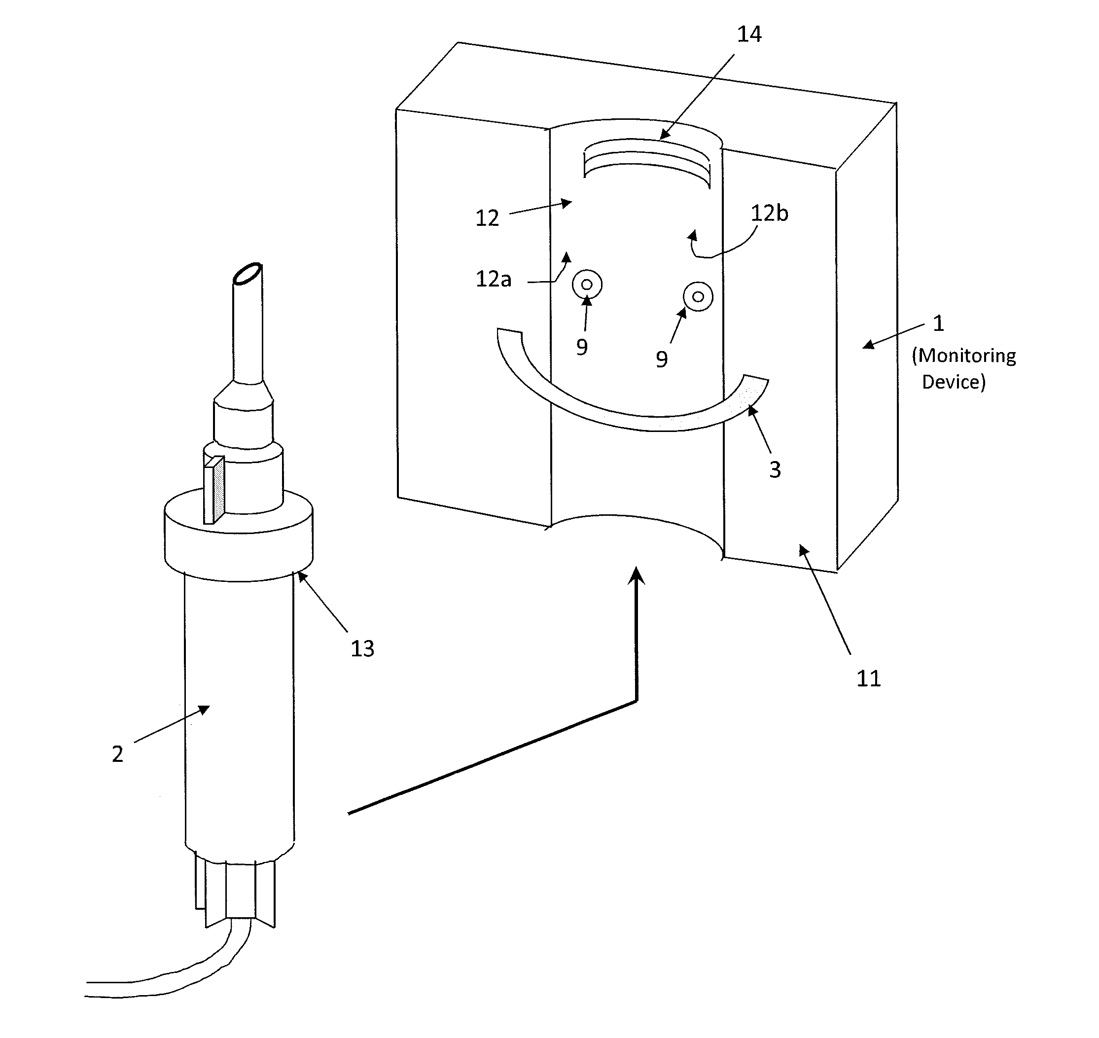
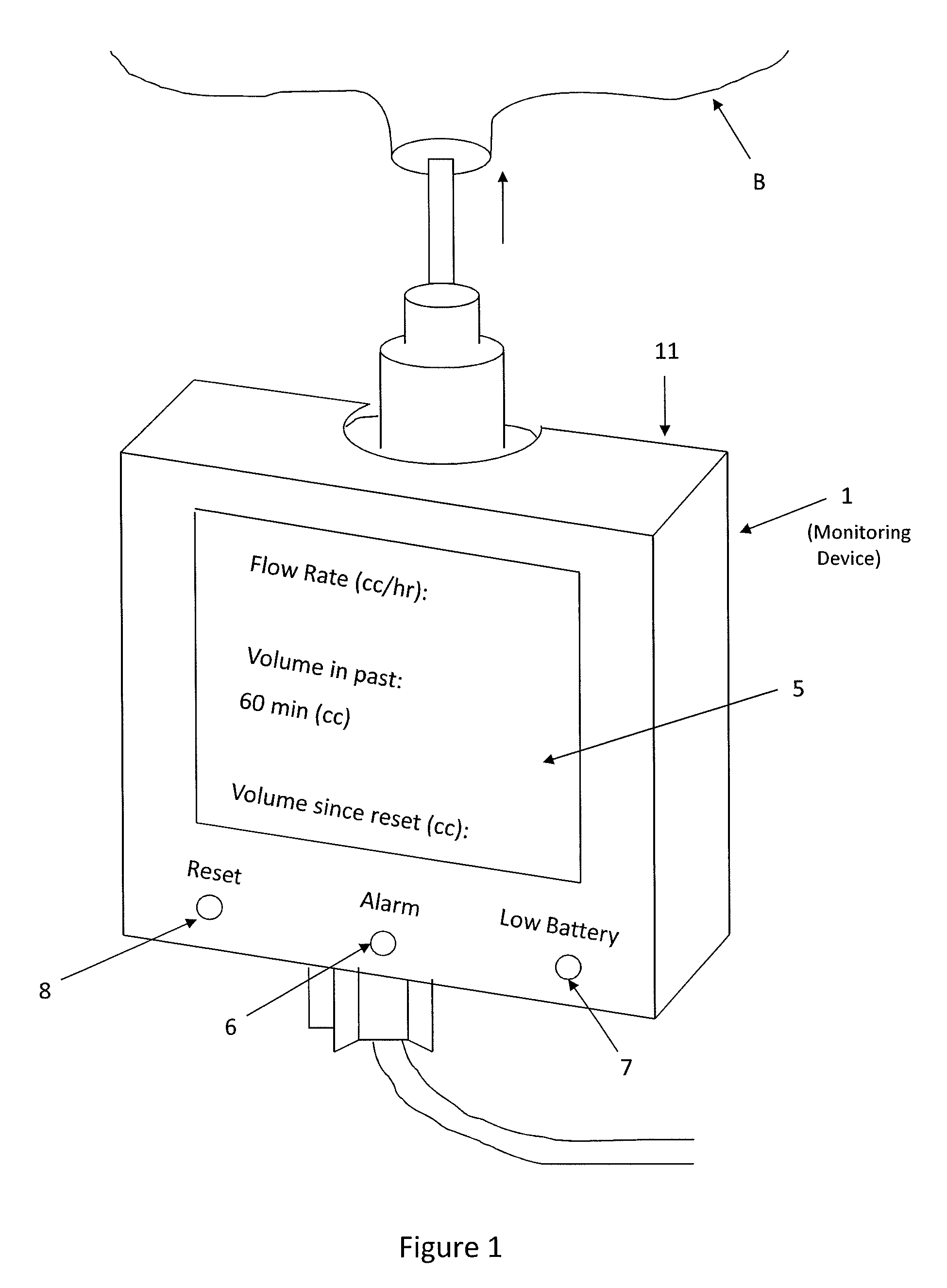
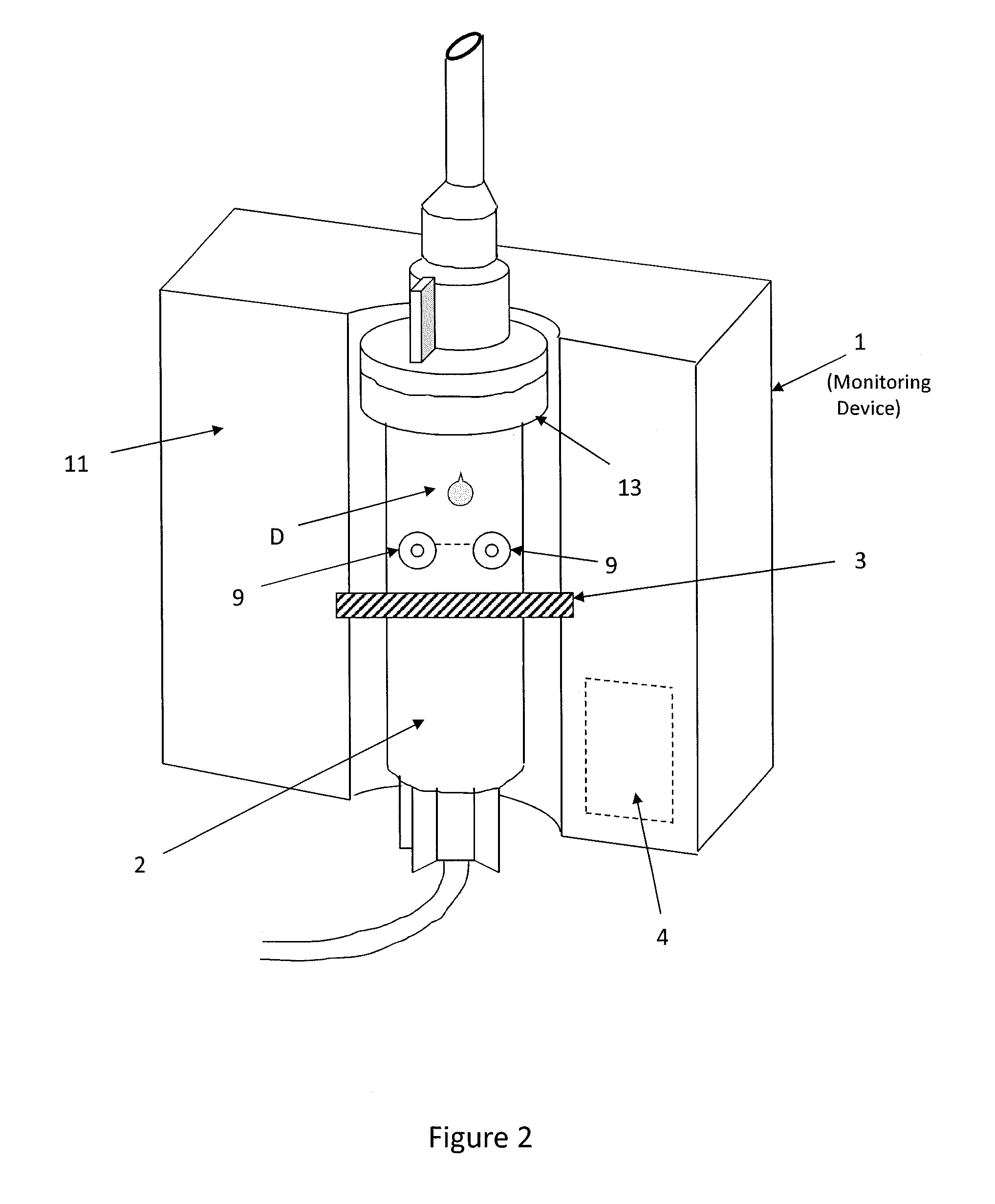
[0014]In general terms, the following provides an automated IV monitoring device that provides real-time monitoring of the actual flow rate, as well as total infused volume from a designated point in time, for example, in the last hour and / or since reset. A display is continually updated to display the flow rate and the infused volume over the predetermined period of time. It has been recognized that by using a processing unit to automatically calculate and display the flow rate and total infused volume in real-time, the nurse can quickly and easily monitor and adjust the flow rate appropriately. The nurse does not have to manually count the drops and estimate the flow rate, rather he or she can simply adjust the set screw and watch the display until the desired flow rate is achieved. For example, in one embodiment, the IV monitoring unit is configured to display the fluid infused in the past hour, as well as since reset (which typically corresponds to the beginning of the nurse's s...


PUM


Abstract

An automated intravenous (IV) monitoring device is provided comprising a sensor for sensing drips passing through an IV drip chamber, a processing unit for calculating the total infused volume over a predetermined period of time, and a display for displaying the total infused volume. The IV monitoring device preferably also calculates and displays the flow rate of the drips. Additionally, an alarm can be activated if the flow rate drops below a predetermined value. A method of providing data pertaining to IV drips being infused into a body is also disclosed.

Description

[0001]This application claims priority from U.S. Provisional Application No. 61 / 184,023 filed on Jun. 4, 2009, the contents of which are incorporated herein by reference.FIELD OF THE INVENTION[0002]The present invention relates generally to intravenous monitoring devices.BACKGROUND[0003]When a patient requires the use of an intravenous (IV) drip for the introduction of various fluids into his or her body, it is common for a physician to prescribe a set flow rate in cubic centimeters per hour (cc / hr). A health care provider, usually a nurse, sets this rate manually by turning a small set screw which is located on the IV tubing connected to the patient. The nurse uses his or her best judgment to manually count the number of drips passing through the drip chamber per unit of time and then estimates the drip rate. The nurse must then mentally convert the drip rate measured in drips / minute to a flow rate measured in cc / hr. If the estimated flow is higher or lower than desired, the nurse ...

Claims


Application Information

Patent Timeline
Patent Type & Authority Patents(United States)
IPC IPC(8): G08B21/00G16H20/17
CPCG01F3/00A61M5/1689G01F15/0755G06F19/3468G01F15/06A61M2205/3306G16H20/17
Inventor WARNER, TOD. H.CARMAN, WAYNE
Owner WARNER TOD H
Learn More