Fuel injector mount

a technology of fuel injectors and mounts, which is applied in the direction of fuel injection apparatus, wear-reducing fuel injection, and feed systems, etc., can solve the problems of premature wear of the injector seal, fuel rail and the fuel injector to pulsate or vibrate, and create undesirable nois

Active Publication Date: 2014-04-22
FORD GLOBAL TECH LLC
View PDF28 Cites 12 Cited by
  • Summary
  • Abstract
  • Description
  • Claims
  • Application Information

AI Technical Summary

Problems solved by technology

High-pressure fuel pumps used in these systems commonly create pressure pulsations that can cause the fuel rail and the fuel injectors to pulsate or vibrate.
This can cause wear and create undesirable noise, especially noticeable at idle speeds.
Vibration also has been known to cause premature wearing of the injector seals between the injector nozzles and the cylinder head.
Forces originating from the structure of a fuel injector can also cause undesirable noise and wear.
Energizing of the magnetic solenoid valve in the injector and the impact of the pin seating at injector closing can create a hammering effect which can cause component wear.
Attempts to alleviate noise and wear problems have included designs for suspending fuel injectors from the fuel rail, but such attempts have been complicated and not flexible enough to be used with various injector designs.

Method used


Image

  • Fuel injector mount
  • Fuel injector mount
  • Fuel injector mount

Examples


Embodiment Construction

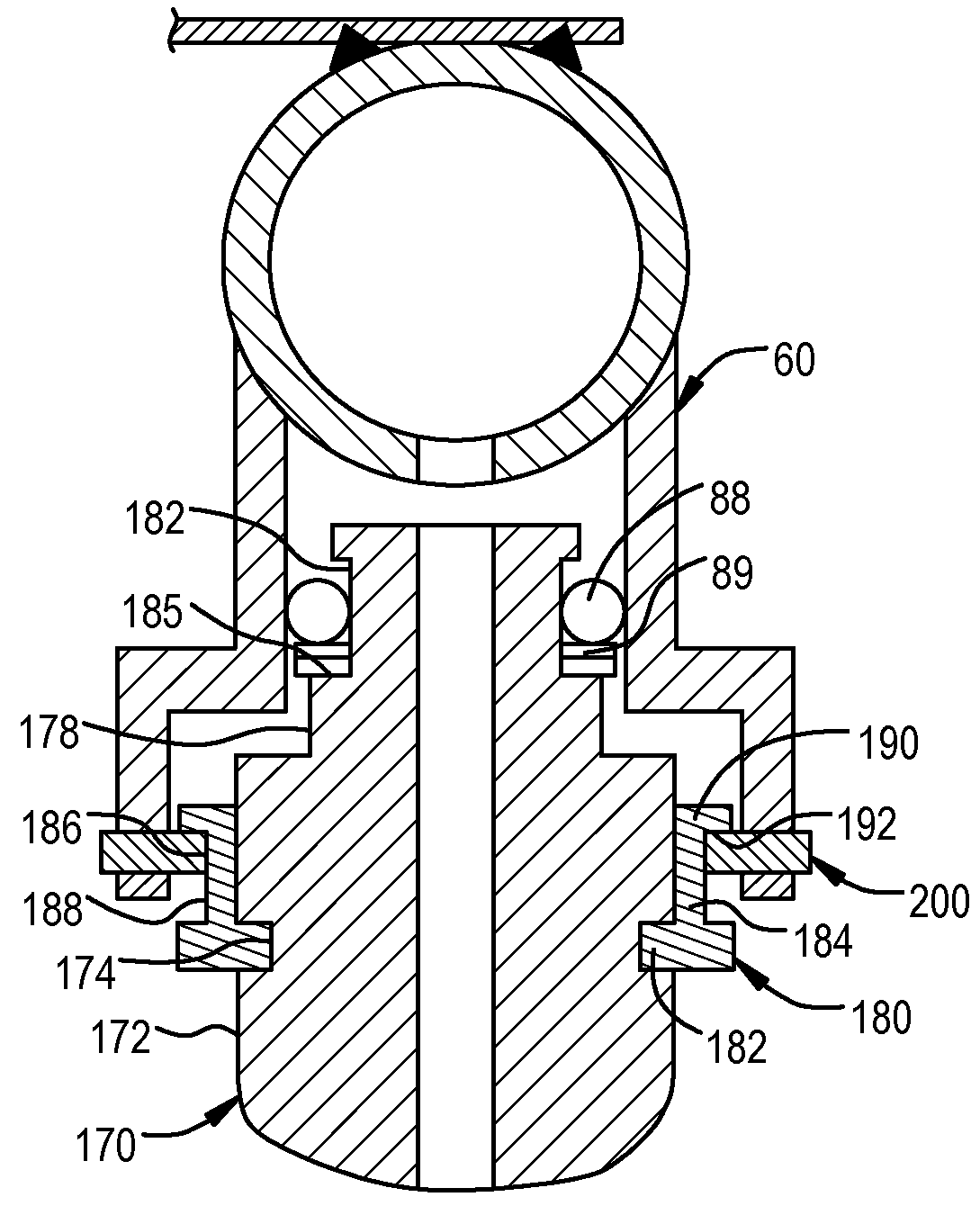
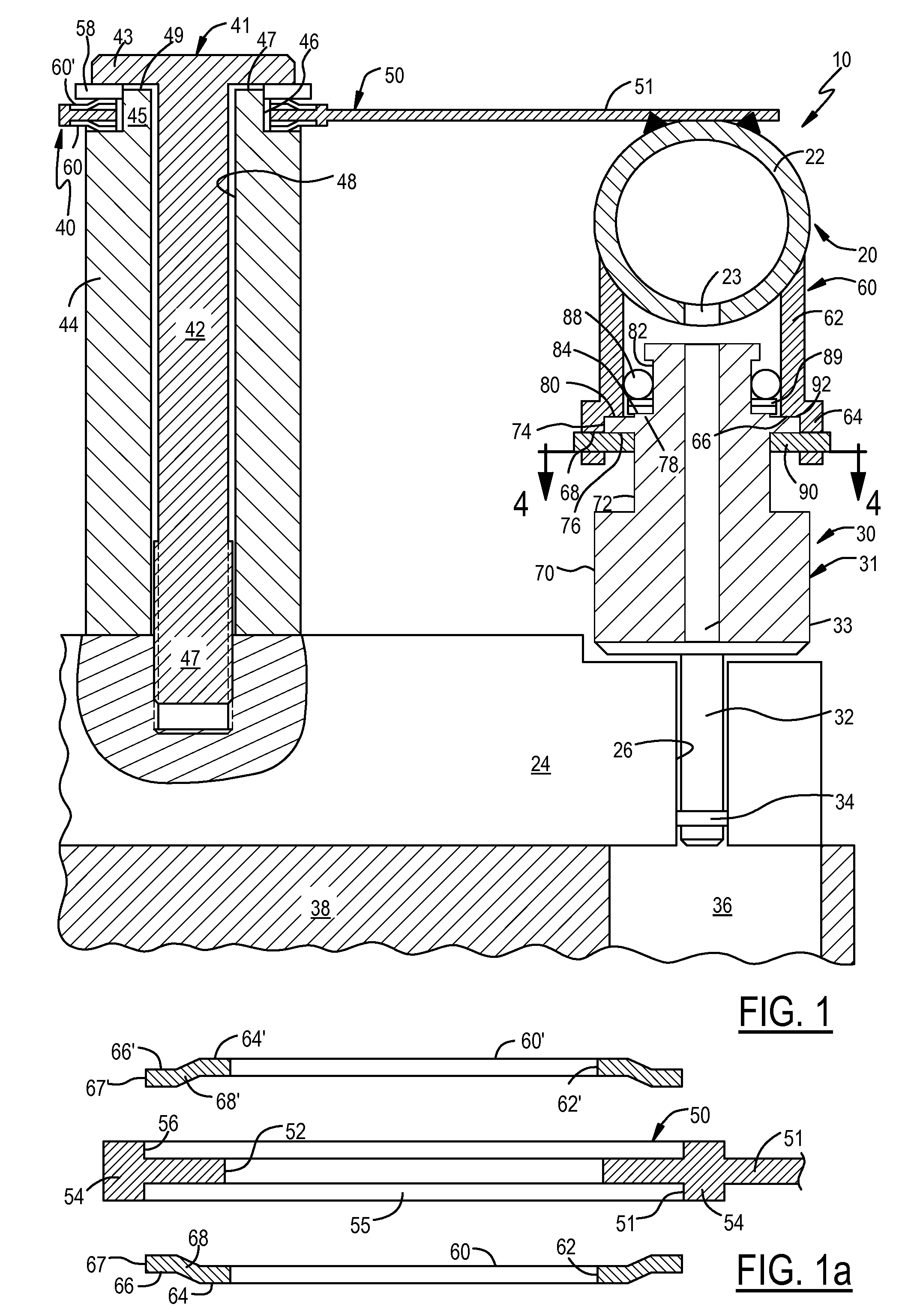
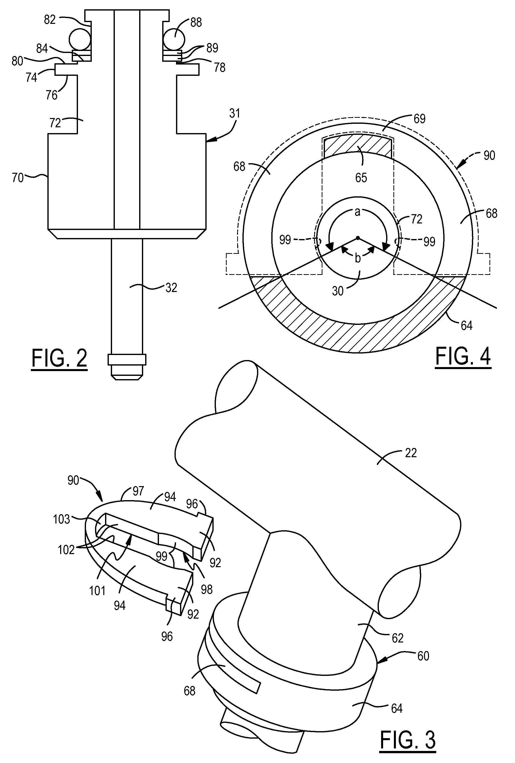
[0016]Referring to FIG. 1, a direct injection fuel injector system 10 includes a fuel rail assembly 20 and a fuel rail 22 having at least one fuel injector cap 60. The fuel rail cap 60 is welded or otherwise secured to the fuel rail 22. A fuel injector 30 is supported within the fuel rail cap 60. The injector 30 is an assembly including a main body 31 and a nozzle 32. The injector 30 is suspended over an internal combustion engine cylinder head 24.

[0017]In FIG. 1, the injector 30 is positioned vertically above the cylinder head 24, but other configurations are within the scope of the present invention. For example, injectors may be positioned horizontally and mounted in the engine block 38 adjacent the combustion chamber 36. In addition, injectors may be mounted at an angle to horizontal or vertical for engines having cylinders oriented in a “V” configuration. Therefore, as used herein, the term “suspended” means that the injector body 31 does not directly contact the cylinder head ...


PUM


Abstract

A direct fuel injection fuel system includes a fuel rail cap and a fuel injector received within the fuel rail cap. A clip extends through slots in the fuel rail cap and engages the fuel rail to support the fuel rail within the fuel rail cap. The fuel rail cap includes a groove adjoining the slots to accept a portion of the clip. The clip engages a shoulder on the fuel injector assembly. The shoulder may be on the injector body or on an adapter secured to the injector body.

Description

FILED OF THE INVENTION[0001]The present invention relates to internal combustion engine fuel injection systems, and more particularly to the mounting of fuel injectors.BACKGROUND OF THE INVENTION[0002]Direct injection is a common type of fuel injection system in which fuel is injected directly into the combustion chambers of an internal combustion engine cylinder by fuel injectors. The fuel injectors are connected to a fuel supply by a fuel rail, typically a tubular member The fuel injectors typically are mounted in fuel injector sockets in the fuel rail. Fuel rails in direct injection fuel systems are commonly mounted on the engine's cylinder head or engine block, with the fuel injectors also mounted on or resting on or in direct contact with the cylinder head or engine block.[0003]A typical fuel injector has a nozzle which extends through the cylinder head for fluid communication with a combustion chamber. A seal is mounted on the nozzle and seals the nozzle against the cylinder h...

Claims


Application Information

Patent Timeline
Patent Type & Authority Patents(United States)
IPC IPC(8): F02M61/14
CPCF02M63/00F02M2200/8023F02M2200/853F02M61/14F02M2200/856F02M55/025F02M2200/857F02M2200/09F02M2200/02F02M55/02
Inventor SOLFERINO, VINCE P.ZENG, PAUL W.BROSTROM, PATRICK C.KAPUT, MICHAEL R.LEHTO, SCOTTAHMED, SYED M.
Owner FORD GLOBAL TECH LLC
Why Eureka
Try Eureka