Thermal chamber for IC chip testing

a technology of ic chips and chambers, which is applied in the direction of washstands, lighting support devices, instruments, etc., can solve the problems of requiring tight temperature control difficult control of the temperature of the ic chip, and slow down, so as to reduce the preheating/precooling time, reduce the downward force of the chip with the socket, and reduce the effect of preheating/precooling

Inactive Publication Date: 2014-04-22
XCERRA
View PDF11 Cites 3 Cited by
  • Summary
  • Abstract
  • Description
  • Claims
  • Application Information

AI Technical Summary

Benefits of technology

[0006]The present invention is a small, lightweight cooling / heating chamber that can be used to test IC chips at a controlled temperature on a bench for device characterization and evaluation. This chamber can be retrofitted for use with existing test equipment and be incorporated into current test protocols without significant modification of the test equipment. The thermal chamber of the present invention is a block that has at least one inlet for a hot or cold fluid to circulate through a closed channel to heat or cool the chip, thereby reducing preheating / precooling, or “soak” time. There is also a second flow path that directly cools or heats the chip while testing. The cooling / heating chamber is designed to mate with a workpress (also referred to as a device nest or device plunger) and a docking interface plate to enclose the IC chip for testing purposes. The chamber can be designed with a ball valve or similar mechanism that controls the input of fluid into the chamber.
[0007]A clamp is also disclosed for use in securing the chip to the workpress, having a lever and pair of linkages that drive the workpress through the docking interface plate and against the chip / socket arrangement. The clamp includes spring mounted inside a block that connects to the workpress that yields a compliance for connecting to the chip. This compliance allows the downward force of the chip with the socket to be lessened, thereby reducing PCB wear and socket wear.

Problems solved by technology

This extra power dissipation makes the task of controlling the temperature of the IC chip very difficult.
Because the operation of an IC chip slows down as the temperature of the IC chip increases, very tight temperature control of the IC chip is required throughout the class test.
If the IC-chip temperature is too high, the operation of the IC chip will get a slower speed rating, resulting in the IC-chip being sold as a lower priced part.
Currently, to control the temperature of the chips during testing, large and expensive machines have been constructed such as those available from Delta Designs of Poway California, for example the ETC handlers (see www.deltad.com).
These machines can cost up to four hundred thousand dollars or more.
The temperature control of such machines requires larger volumes to be heated or cooled, and require large allocations of space and capital to operate.

Method used


Image

  • Thermal chamber for IC chip testing
  • Thermal chamber for IC chip testing
  • Thermal chamber for IC chip testing

Examples


Embodiment Construction

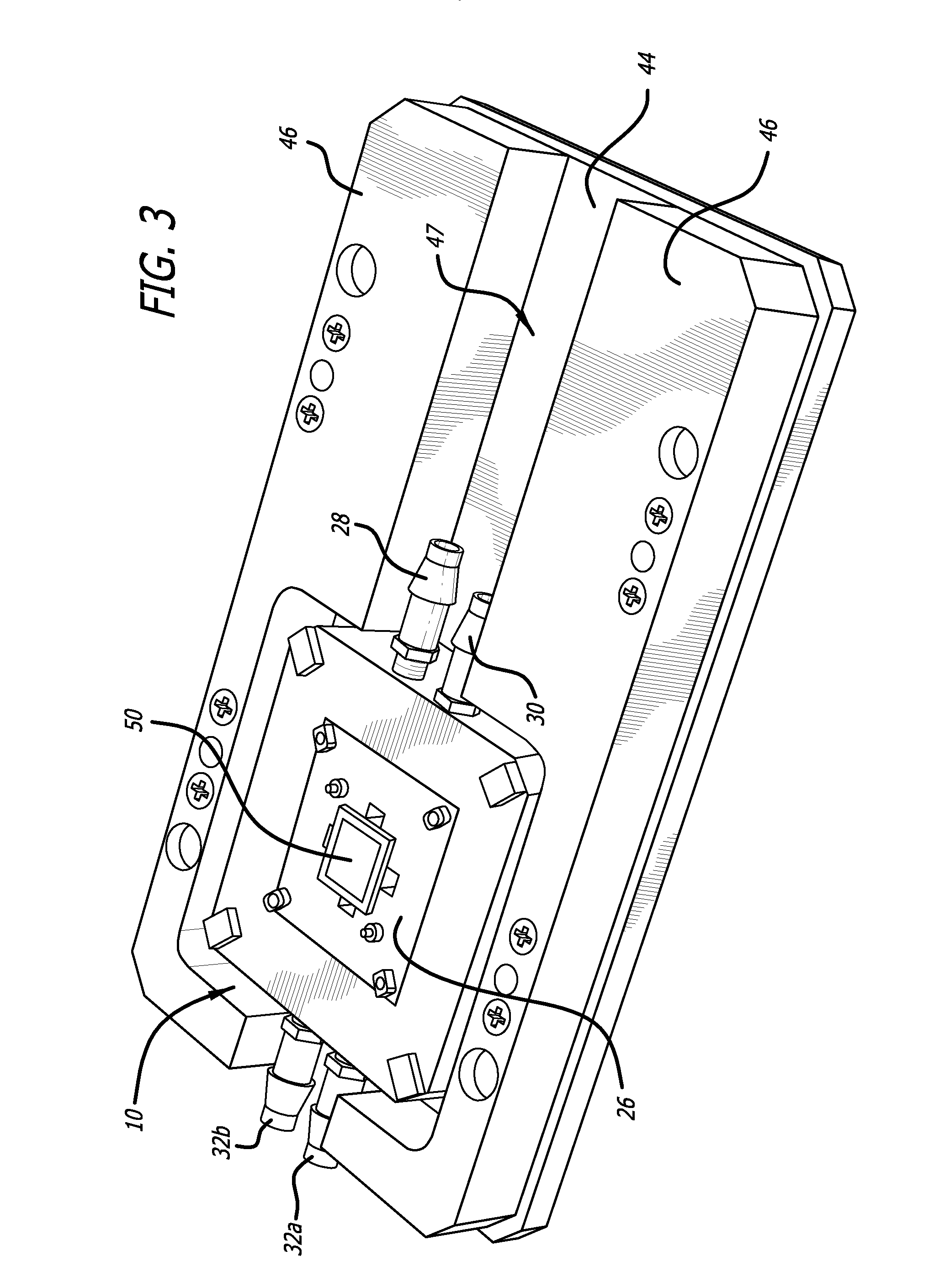
[0016]The present invention is a thermal chamber that can be used to control the temperature of an IC chip under test. The temperature control uses a flow of fluid, which is preferably a cooled or heated gas such as air, nitrogen, or the like. The thermal chamber is designed to hold a chip socket, that itself contains an IC chip to be tested. The thermal chamber is mounted to a docking interface plate that includes a thermal insulator surrounding the thermal chamber. A work press engages a valve actuator on the thermal chamber to introduce fluid across the socket / chip surface.

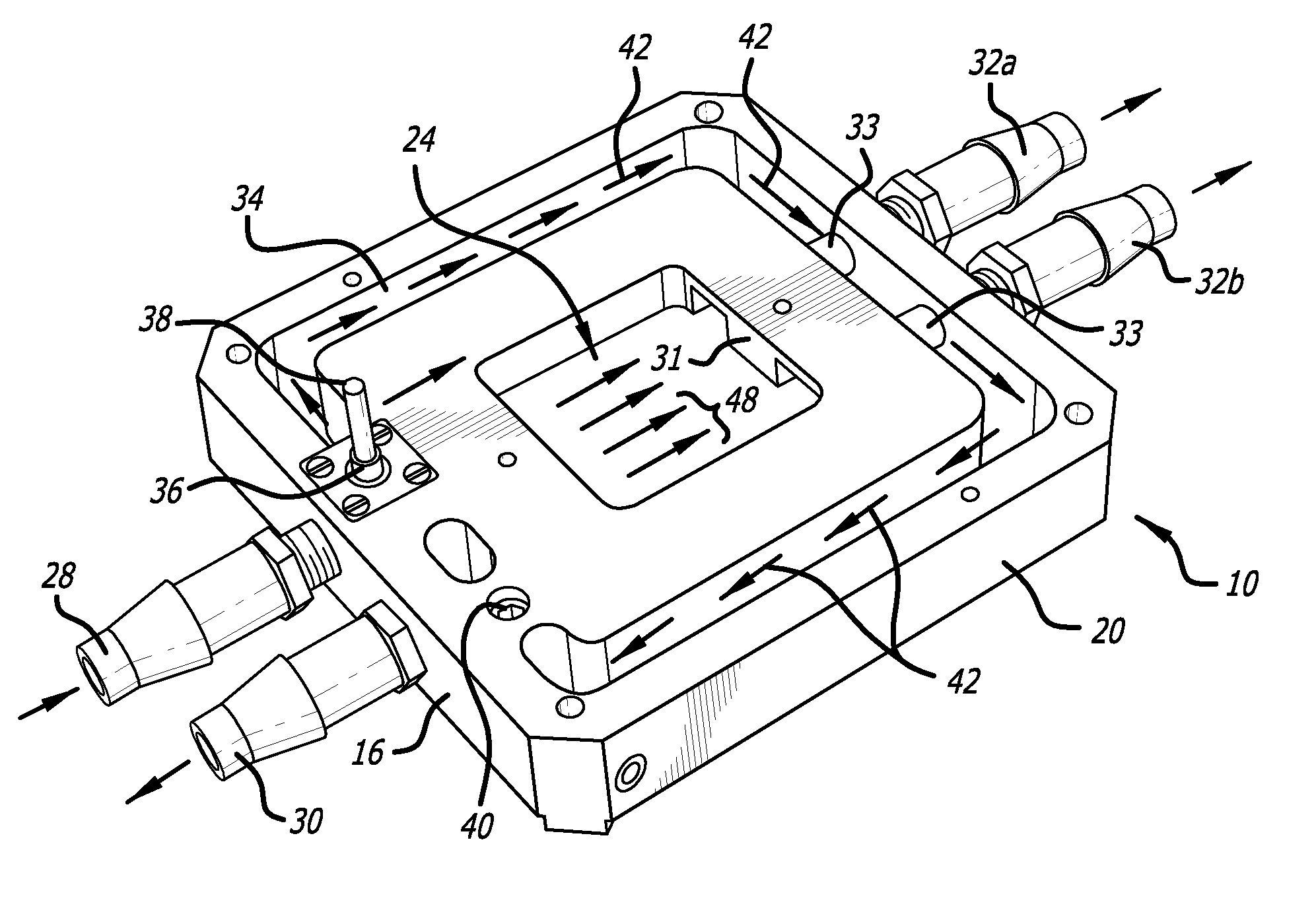
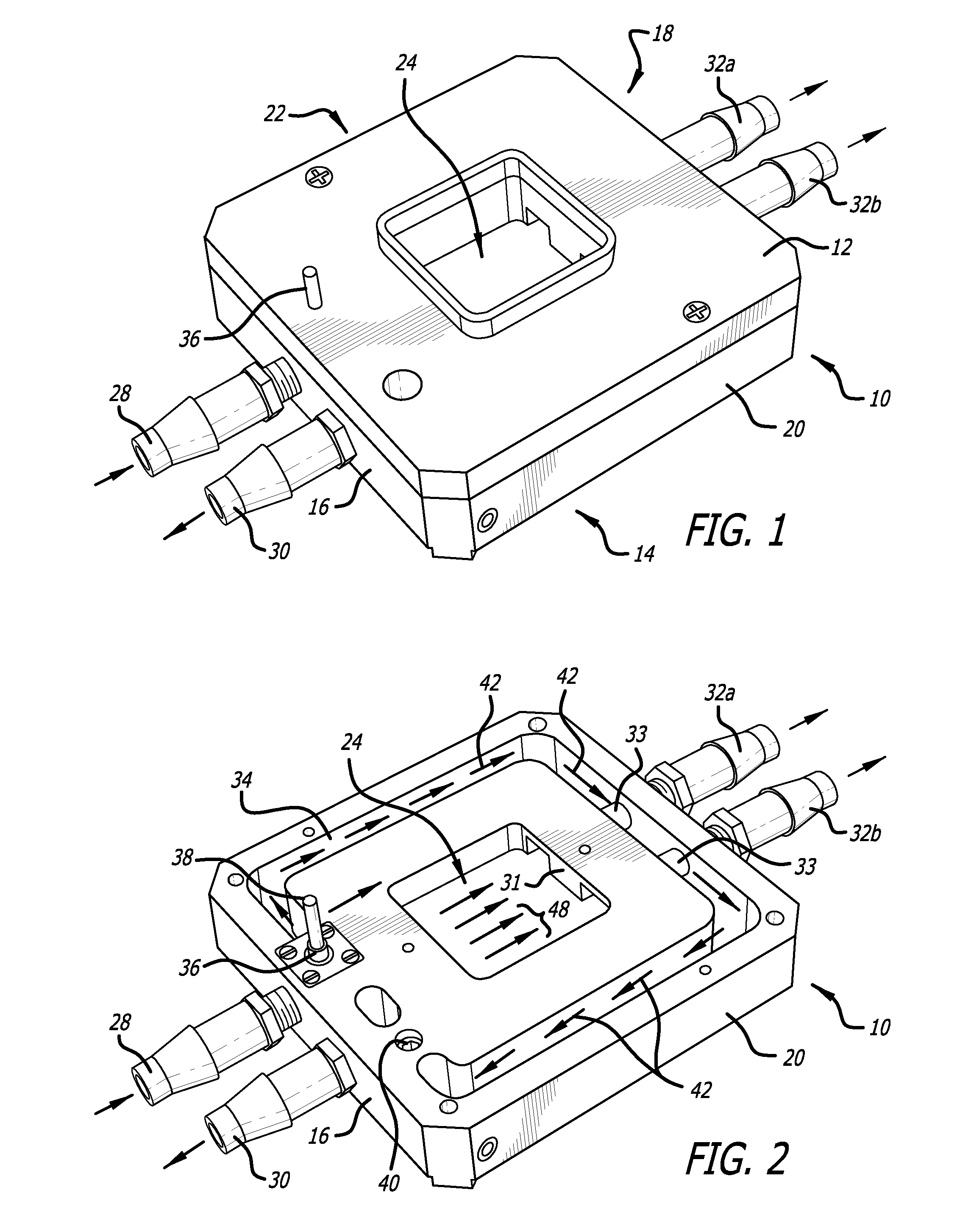
[0017]FIG. 1 is a perspective view of the thermal block 10 that defines the thermal chamber. The thermal block 10 has a top side 12 and a bottom side 14, and front 16 and rear 18 walls along with first and second side walls 20,22. An aperture 24 in the interior of the block 10 allows a chip socket 26 to be inserted and held therein. The front wall 16 of the block 10 includes first and second nozzles 28, 30 that...


PUM


Abstract

A thermal chamber and system for influencing the temperature of an IC chip under test including a thermal block that receives a chip socket, the thermal block adapted to be disposed between a docking interface plate and a workpress. The thermal block receives a flow of heated or cooled gas, and causes an IC chip to become heated or cooled prior to and during a test of the chip. The thermal chamber and system allows an IC chip to be testing under specific temperature conditions without using an expensive handler costing hundreds of thousands of dollars.

Description

BACKGROUND[0001]The present invention is related generally to testing apparatus for integrated circuit chips (“IC chip” or “chip”), and more particularly to an assembly for regulating the temperature of an IC chip while the chip is mounted on a testing board so that it can be tested under predetermined temperature conditions.[0002]Current IC chips can be designed to include hundreds of thousands of transistors, and those transistors require testing before the IC chip is delivered to a customer. Typically, each IC chip is incorporated into an integrated circuit module (IC module), and then the IC-chip in the IC-module is tested with a “burn-in” test, a “class” test, and a “system level” test. Electrical terminals are provided on the substrate which are connected by microscopic conductors in the substrate to the IC chip. The “burn-in” test thermally and electrically stresses the IC chips to accelerate “infant mortality” failures. The stressing causes immediate failures that otherwise ...

Claims


Application Information

Patent Timeline
Patent Type & Authority Patents(United States)
IPC IPC(8): F28F27/02
CPCF28F27/00F16B2/185F28F2200/00G01R31/2874G01R31/28F28F3/12G01R1/0458
Inventor TIENGTUM, PONGSAKPAZ, ENRIQUE
Owner XCERRA
Why Eureka
Try Eureka