Color display architecture and driving methods

a technology of color display and driving method, applied in the field of color display, can solve the problems of inacceptable choice of display device, inability to achieve color saturation, and relatively dim white sta

Active Publication Date: 2014-04-22
E INK CORPORATION
View PDF106 Cites 92 Cited by
  • Summary
  • Abstract
  • Description
  • Claims
  • Application Information

AI Technical Summary

Problems solved by technology

The most significant disadvantage of such a technique is that since each of the sub-pixels has a reflectance of about one third (⅓) of the desired white state, the white state is fairly dim.
Brighter colors can be achieved by adding light from the white pixel, but this is achieved at the expense of color gamut to cause the colors to be very light and unsaturated.
Even with that, the white light level is normally substantially less than half of that of a black and white display, rendering it an unacceptable choice for display devices, such as e-readers or displays that need well readable black-white brightness and contrast.
This dual mode design requires a special circuitry structure within each sub-pixel, which may reduce backplane yield and affect costs.

Method used


Image

  • Color display architecture and driving methods
  • Color display architecture and driving methods
  • Color display architecture and driving methods

Examples


Embodiment Construction

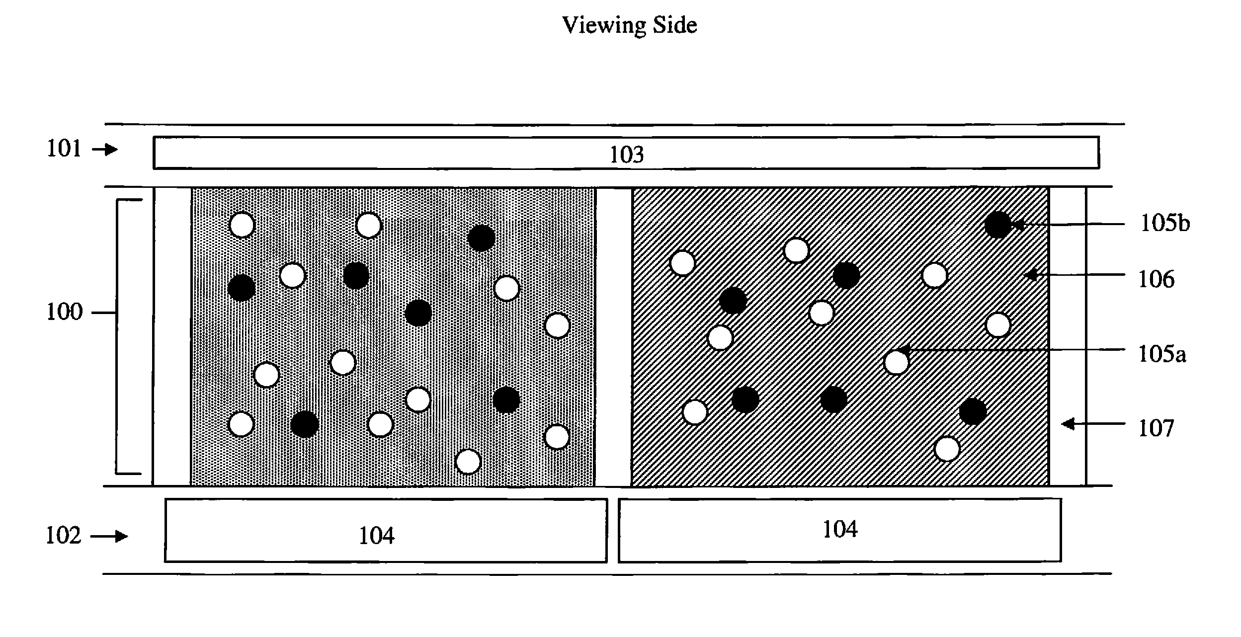
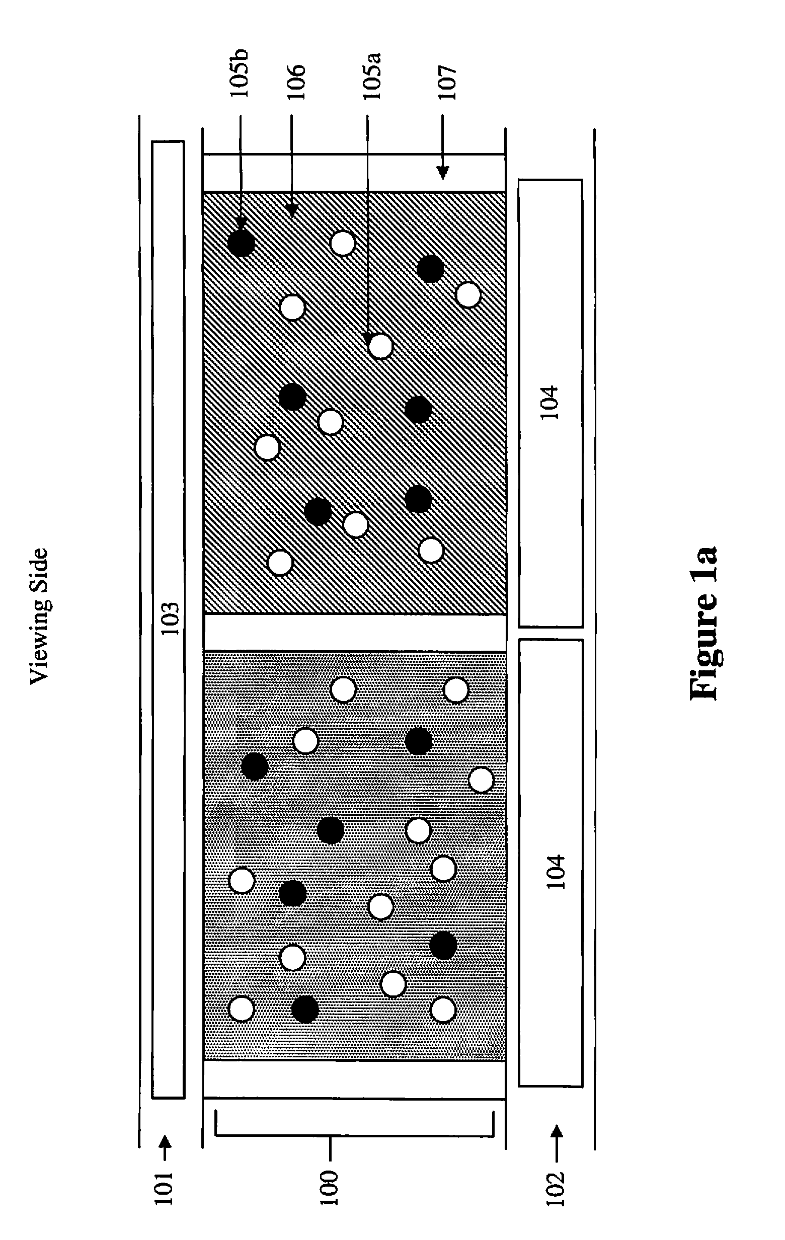
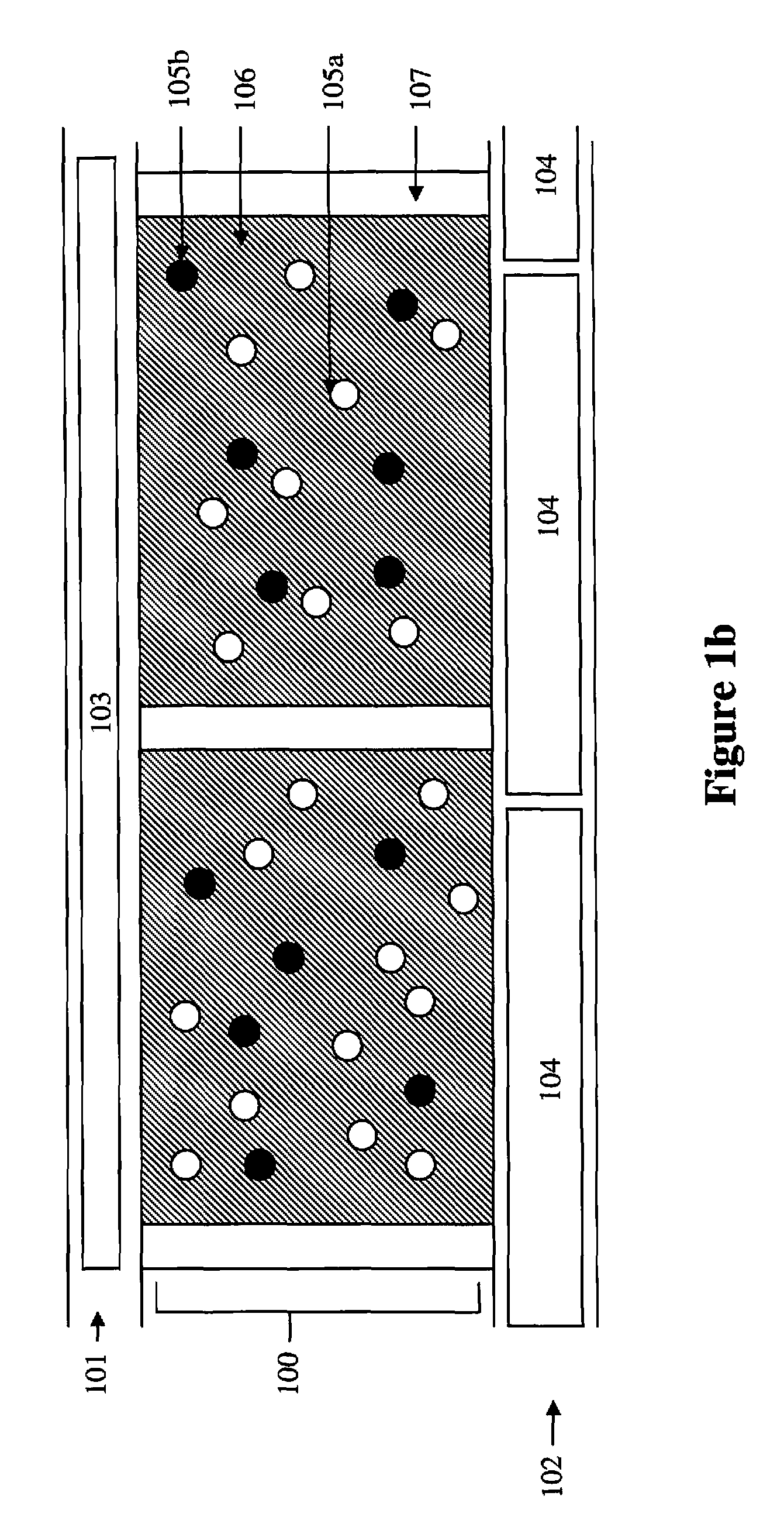
[0017]FIGS. 1a and 1b depict a cross-section view of color display devices of the present invention. A display cell (100) is sandwiched between a first layer (101) and a second layer (102). The display cell (100) is surrounded by partition walls (107). The first layer comprises a common electrode (103). The second layer comprises a pixel electrode (104).

[0018]The display cells of the present invention are filled with an electrophoretic fluid which comprises two type of pigment particles (105a and 105b) dispersed in a solvent or solvent mixture (106). The two types of pigment particles are of contrast colors and oppositely charged. The electrophoretic fluid (or the solvent or solvent mixture in which the pigment particles are dispersed) may be colored (e.g., red, green or blue).

[0019]The common electrode (103) is usually a transparent electrode layer (e.g., ITO), spreading over the entire top of the display device.

[0020]The second layer (102) comprises a pixel electrode (104). The pi...


PUM


Abstract

A method for driving a display cell filled with an electrophoretic fluid comprising two types of pigment particles carrying opposite charge polarities and of two contrast colors wherein said two types of pigment particles are dispersed in a solvent of a color, which method comprises driving said display cell to a color state which color is the color of the solvent by applying a driving voltage which is about 1 to about 20% of the full driving voltage.

Description

[0001]This application claims the benefit of U.S. Provisional Application No. 61 / 348,570, filed May 26, 2010; the content of which is incorporated herein by reference in its entirety.FIELD OF THE INVENTION[0002]The present invention is directed to a color display and methods for driving such displays.BACKGROUND OF THE INVENTION[0003]In order to achieve a color display, color filters are often used. The most common approach is to add color filters on top of black / white sub-pixels of a pixellated display to display the red, green and blue colors. When a red color is desired, the green and blue sub-pixels are turned to the black state so that the only color displayed is red. When the black state is desired, all three-sub-pixels are turned to the black state. When the white state is desired, the three sub-pixels are turned to red, green and blue, respectively, and as a result, a white state is seen by the viewer.[0004]The most significant disadvantage of such a technique is that since e...

Claims


Application Information

Patent Timeline
Patent Type & Authority Patents(United States)
IPC IPC(8): G09G3/34
CPCG02F2001/1678G09G3/344G02F2203/34
Inventor LIN, CRAIG
Owner E INK CORPORATION
Why Eureka
Try Eureka