Method and force-limiting handle mechanism for a surgical instrument

a technology of limiting handle and surgical instrument, which is applied in the direction of surgical forceps, surgical staples, paper/cardboard containers, etc., can solve the problems of excessive damage to the tissues being operated, damage to the tissue, and damage to the instrument itsel

Active Publication Date: 2014-04-29
TYCO HEALTHCARE GRP LP
View PDF507 Cites 957 Cited by
  • Summary
  • Abstract
  • Description
  • Claims
  • Application Information

AI Technical Summary

Problems solved by technology

During the performance of certain surgical procedures with the above described surgical instruments, application and transmission of force from the handle assemblies to the end effectors may ultimately result in excessive damage to the tissues being operated on.
For example, when grasping instruments are utilized to manipulate tissue, excessive force applied to tissue may inadvertently cause damage to tissue.
In addition to the potential for damaging tissue due to excessive force transmitted from the handle assembly to the end effector of a surgical instrument, damage may also occur to the instrument itself.
This may occur where the tissue being operated on is sufficiently stiff or hard such that it cannot be compressed or cut by the surgical instrument.
Additionally, certain hard tissues may not be able to be penetrated by the amount of force applied to fasteners in situations where stapling of tissue is desired.
Similarly, instruments may not be able to completely compress the tissues where compression of tissues is required during the application of surgical clips.
Improper positioning of the cartridge assemblies on the surgical instrument, or malfunction of the cartridge assemblies themselves, may result in a resistance of the surgical instrument to application of pressure on the trigger of a handle assembly thereby causing damage to the surgical instrument itself.
This may also occur where the cartridge assembly is devoid of fasteners and the surgeon attempts to continue or reuse the surgical instrument.

Method used


Image

  • Method and force-limiting handle mechanism for a surgical instrument
  • Method and force-limiting handle mechanism for a surgical instrument
  • Method and force-limiting handle mechanism for a surgical instrument

Examples


Embodiment Construction

[0029]An embodiment of the presently disclosed handle assembly incorporating a force-limiting handle mechanism will now be described in detail with reference to the drawings wherein like numerals designate identical or corresponding elements in each of the several views. As is common in the art, the term “proximal” refers to that part or component closer to the user or operator, e.g., surgeon or physician, while the term “distal” refers to that part or component farther away from the user.

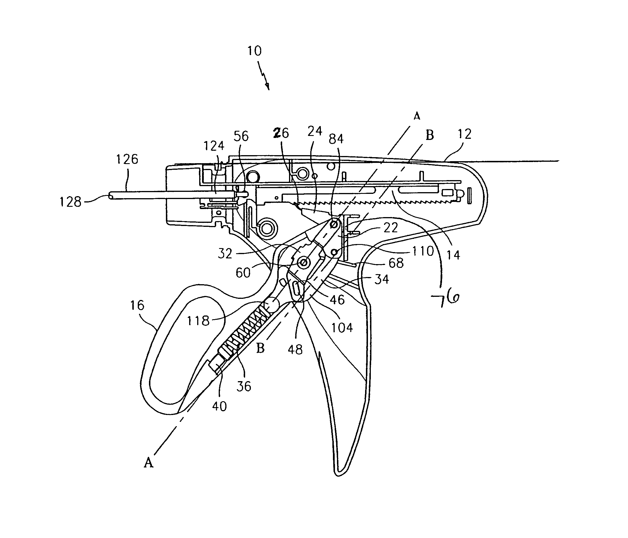
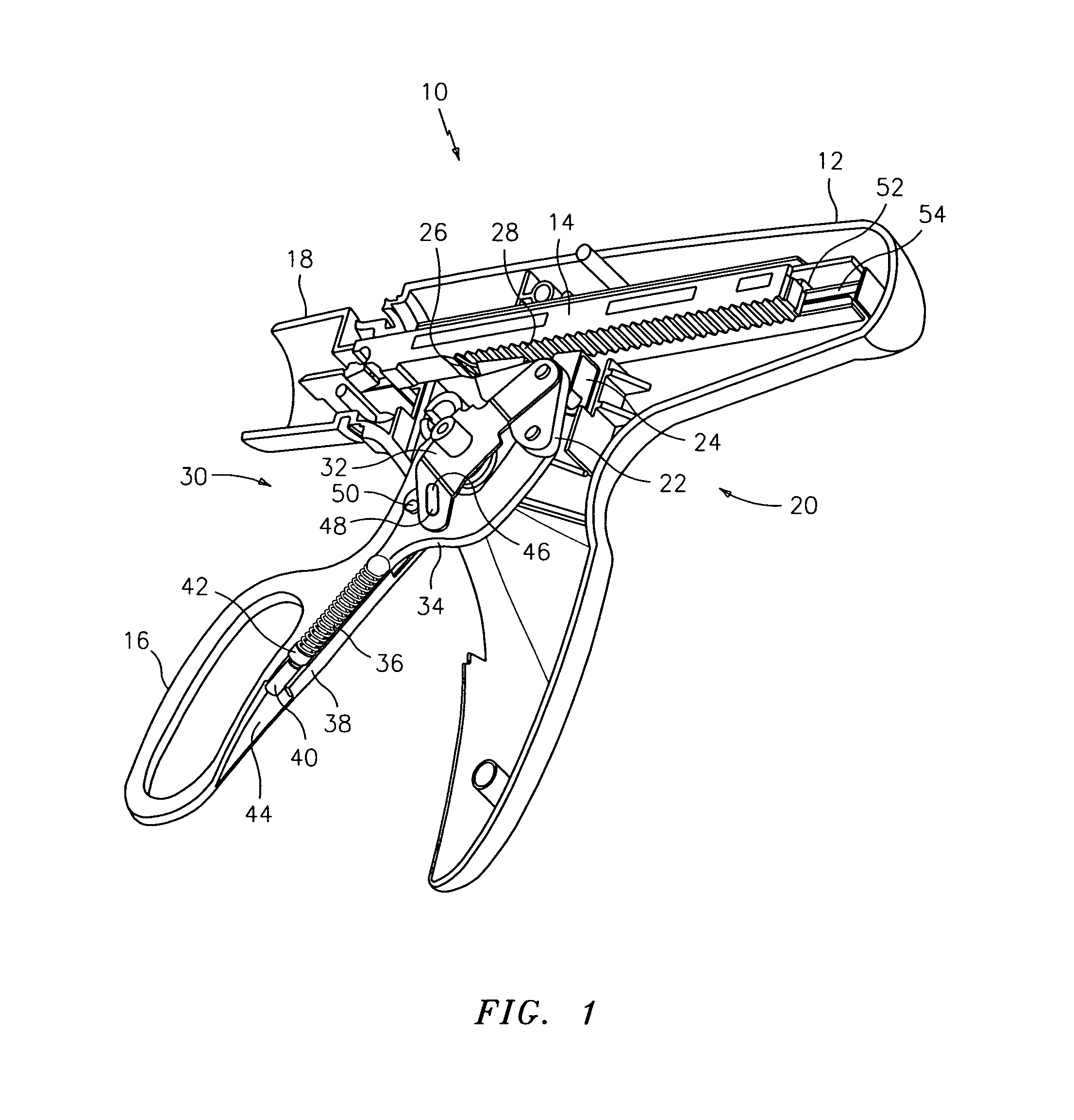
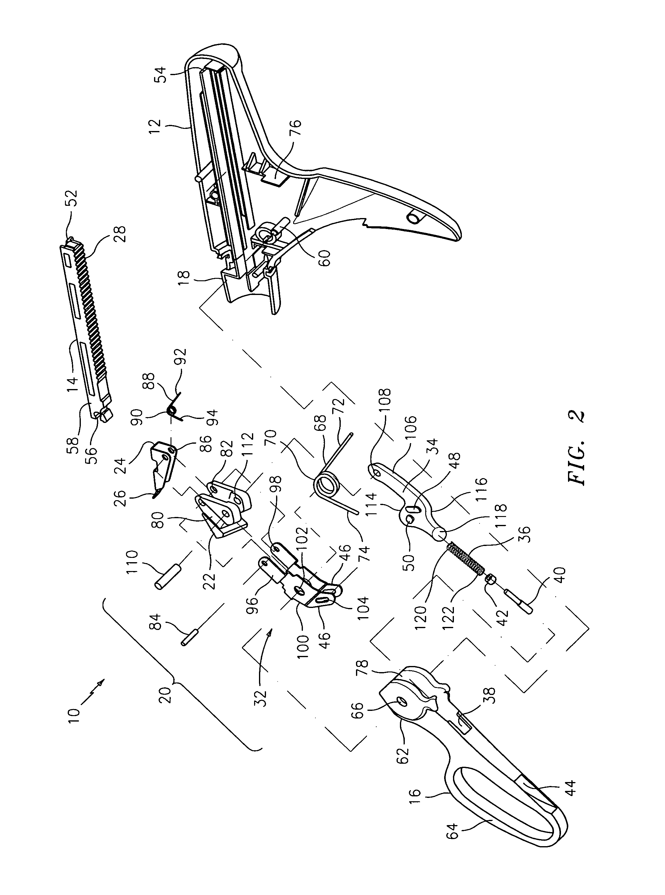
[0030]Referring initially to FIG. 1, there is disclosed a handle assembly 10 for use with a surgical instrument. Handle assembly 10 incorporates an adjustable force-limiting mechanism 30 (e.g., clutch) to prevent excessive force applied to tissue and to prevent damage to handle assembly 10 itself in the event of an overload condition present at an associated end effector. Handle assembly 10 is particularly suitable for use in surgical instruments incorporating end effectors, such as clip or staple ...


PUM

PropertyMeasurementUnit
forceaaaaaaaaaa
pressureaaaaaaaaaa
hardaaaaaaaaaa

Abstract

A safety handle assembly for use with a surgical instrument having an operative distal end portion is disclosed. The handle assembly includes a handle housing and a drive element movably mounted within the handle housing and connected to an associated operative distal end portion. A drive assembly is positioned within the handle housing and is engageable with the drive element to move the drive element within the handle housing. An actuator is movably mounted on the handle housing and an adjustable force-limiting mechanism is interposed between the drive assembly and the actuator. A force-limiting mechanism releasably connects the actuator to the drive assembly. The force-limiting mechanism is adjustable to preset the force at which the actuator separates or breaks away from the drive assembly.

Description

BACKGROUND[0001]1. Technical Field[0002]The present disclosure relates to a method and handle assembly for use with a surgical instrument. More particularly, the present disclosure relates to a method and handle assembly incorporating a force-limiting handle mechanism for use with a surgical instrument having a distal end effector.[0003]2. Background of Related Art[0004]Various instruments are used during surgical procedures to manipulate tissue. Some of these instruments incorporate a handle assembly which is provided to transmit a force to an end effector applied to tissue. For example, some surgical instruments may be provided with a pair of jaws on the distal end to grasp or cut various tissues. Operation of the handle assembly opens and closes the jaws by transmitting a force from a trigger mechanism associated with the handle assembly to the jaws and thus to the tissue. Other types of surgical instruments may be provided with fastener applying end effectors which are configure...

Claims


Application Information

Patent Timeline
Patent Type & Authority Patents(United States)
IPC IPC(8): A61B17/064A61B17/00
CPCA61B17/2909A61B17/068A61B17/10A61B19/30A61B2017/2912A61B2017/292A61B2017/2923A61B2017/2925A61B90/03Y10T74/20612
Inventor ZEMLOK, MICHAELSCIRICA, PAUL A.DESANTIS, ROBERT J.
Owner TYCO HEALTHCARE GRP LP
Why Eureka
Try Eureka