System and method for applying plasma sparks to tissue

a plasma spark and tissue technology, applied in the field of minimally invasive methods, can solve problems such as tissue damage caused by sparks, and achieve the effect of minimal collateral damage and clean and precis

Active Publication Date: 2014-04-29
OLD DOMINION UNIVERSITY RESEARCH FOUNDATION
View PDF31 Cites 8 Cited by
  • Summary
  • Abstract
  • Description
  • Claims
  • Application Information

AI Technical Summary

Benefits of technology

[0009]The device and method achieve a high level of precision through the generation of a spark discharge between at least two electrodes. Electrode configuration and distance determine the extent and location of the incision. Electrode separations can be as small as fractions of a millimeter and up to a centimeter or more (e.g., 3 centimeters). The spark originates from the sharpest tip or edge along these electrodes and along the shortest distance between the electrodes. This allows the design of minimally invasive systems that can be combined, for example, with a catheter to reach and treat internal organs. The system also permits the delivery of the spark with electrodes that penetrate through layers of tissue to the site that is to be treated.
[0015]Generally, the medium for the wave propagation associated with the pulse generator is a continuous dielectric, such as found in coaxial cables, which are often used in a PFL. Use of cables in the PFL facilitates the generation of pulses having a desired duration. This is because, in a PFL, the pulse duration is determined by the length of the cable that is used and only cables of certain lengths are practical. The medium or cable associated with the pulse generator can be characterized by impedance and capacitance per unit length. Such an arrangement provides a fast rise time that approximates zero and can be as short as 1 nanosecond.
[0021]During the application of tissue conditioning pulses, the tissue impedance may gradually decrease. If the impedance of the pulse generator is not matched by a resistor in parallel to the treated tissue, the amplitudes of the train of pulses that are applied to the tissue will change accordingly. Generally, this will not affect the ability to damage the tissue with a spark. However, if the tissue impedance is initially much higher than the impedance of the pulse generator, pulse trains with amplitudes much higher than the charging voltage can be applied in order to produce tissue characteristics that enable breakdown faster than lower voltages. Alternately, by monitoring the pulse amplitudes, it is possible to compensate for this effect by changing the voltage that is used to charge the pulse generator during the exposure.

Problems solved by technology

The damage to the tissue by the spark is caused by the rapid conversion and input of the available electrical energy into the tissue (i.e., the discharge medium).

Method used


Image

  • System and method for applying plasma sparks to tissue
  • System and method for applying plasma sparks to tissue
  • System and method for applying plasma sparks to tissue

Examples


example 1

Treatment of Cellulite

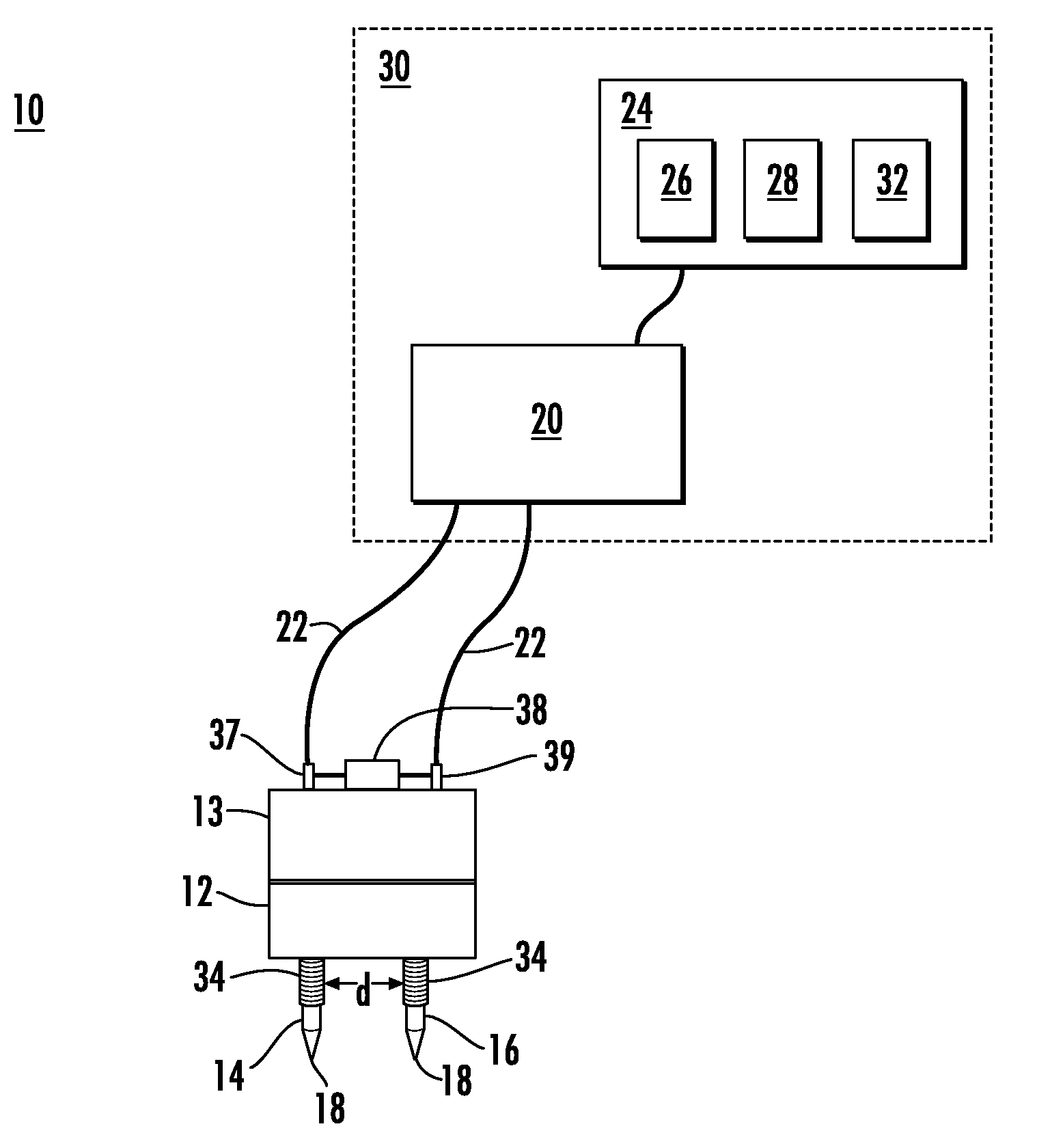
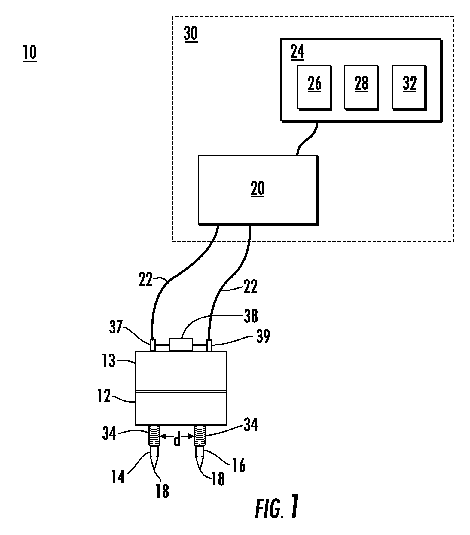
[0122]The area on skin that is affected by cellulite dimples or folds was identified by the clinician and, where desired, the clinician used a dermal marker to delineate the dimples. Electrodes, such as those shown in FIG. 10, made of conducting material such as metals and for example, 27G, were inserted into the tissue. Then, after selection of treatment parameters, pulses were delivered at a desired repetition rate, for example, 10 Hz. The proximal parts of the microneedles were insulated with a material that has a high voltage breakdown threshold, such as poly(p-xylylene) polymers sold by Para Tech Coating, Inc., under the PARYLENE trademark. The distal part is bare, i.e., uninsulated. Typically, the first few pulses acted as pre-plasma tissue conditioning pulses (example, 5-100 pulses), which changed the electrical characteristics of the tissue between the electrodes. This was evidenced by a decrease in resistance that ultimately resulted in conditions lead...

example 2

Cutting of Tissue

[0123]The adipose tissue of a pig was cut using the apparatus shown in FIG. 10 and method of the present invention. A picture of this cut is shown in FIG. 4. The individual marks on the ruler in FIG. 4 are 1 mm apart. This tissue cut was achieved using 0.40 J / spark delivered at 12.5 kV pulse voltage. Two partially insulated electrode needles, separated by 7 mm, were used. Eight (8) mm of the length of the needles were inserted into the tissue. Of the 8 mm length, the proximal 6 mm length of the electrode needles were coated with polyester insulation (other materials for insulation can also be used, for example, Parylene) and the distal 2 mm length were bare, i.e., uninsulated. The source impedance was 125 Ohm and the system was matched. The pulse duration was 327 ns. To cut the tissue, 34 pre-plasma tissue-conditioning pulses were applied followed by 20 sparks.


PUM


Abstract

A pulse delivery system for producing a spark in tissue is disclosed. The system can include at least two electrodes having sharp surface features, where the at least two electrodes are electrically isolated from one another. The sharp features of the electrodes can be separated by a distance of about 2 to 20 mm. The system can also include a pulse generator for delivering pulsed voltage differences between the at least two electrodes. The pulsed voltage differences can producing a voltage difference ranging from about 2.5 kV to about 35 kV for a duration of about 50 ns to 3 μs. The system can include a controller for determining whether the plurality of pulsed voltage differences produced a spark between the at least two electrodes. A method of producing a spark in tissue for both therapeutic and cosmetic, i.e., non-therapeutic, applications is also disclosed.

Description

CROSS-REFERENCE TO RELATED APPLICATIONS[0001]This application claims priority to U.S. Provisional Application No. 61 / 169,013, entitled “Method and System for Damaging and Cutting Tissue With Plasma Sparks,” filed Apr. 14, 2009, the entirety of which is incorporated herein by reference.BACKGROUND OF THE INVENTION[0002]1. Technical Field[0003]The present invention relates to a minimally invasive method for cutting, damaging and destroying selected cells or portions of tissue. More particularly, the present invention relates to the use of electrodes to create a plasma spark to cut, damage, and destroy cells or portions of selected tissue.[0004]2. Related Art[0005]The inventors have developed the present invention, which overcomes the drawbacks of prior art techniques and provides a new technique for cutting, damaging, ablating and destroying tissue that does not need to be carried out in a specialized medium, operates at low energy, and minimizes collateral damage to surrounding tissue...

Claims


Application Information

Patent Timeline
Patent Type & Authority Patents(United States)
IPC IPC(8): A61B18/12
CPCA61B2018/00827A61B18/1477A61B2018/00892A61B2018/00875A61B18/1206A61B2018/1213A61B2018/122
Inventor JUERGEN, KOLB FNOAH, SCULLYKARL, SCHOENBACH HPAITHANKAR, DILIP
Owner OLD DOMINION UNIVERSITY RESEARCH FOUNDATION
Why Eureka
Try Eureka