
Machine vision systems for use with programmable material consolidation apparatus and systems

a technology of programmable material and machine vision, applied in the direction of program control, additive manufacturing process, instruments, etc., can solve the problems of conventional stereolithographic apparatus without machine vision system for ensuring, conventional stereolithographic apparatus without handling system, and cleaning equipment suitable for use with relatively delicate structures. achieve the effect of high level of precision

Inactive Publication Date: 2005-03-03
MICRON TECH INC
View PDF54 Cites 8 Cited by
  • Summary
  • Abstract
  • Description
  • Claims
  • Application Information

AI Technical Summary

Benefits of technology

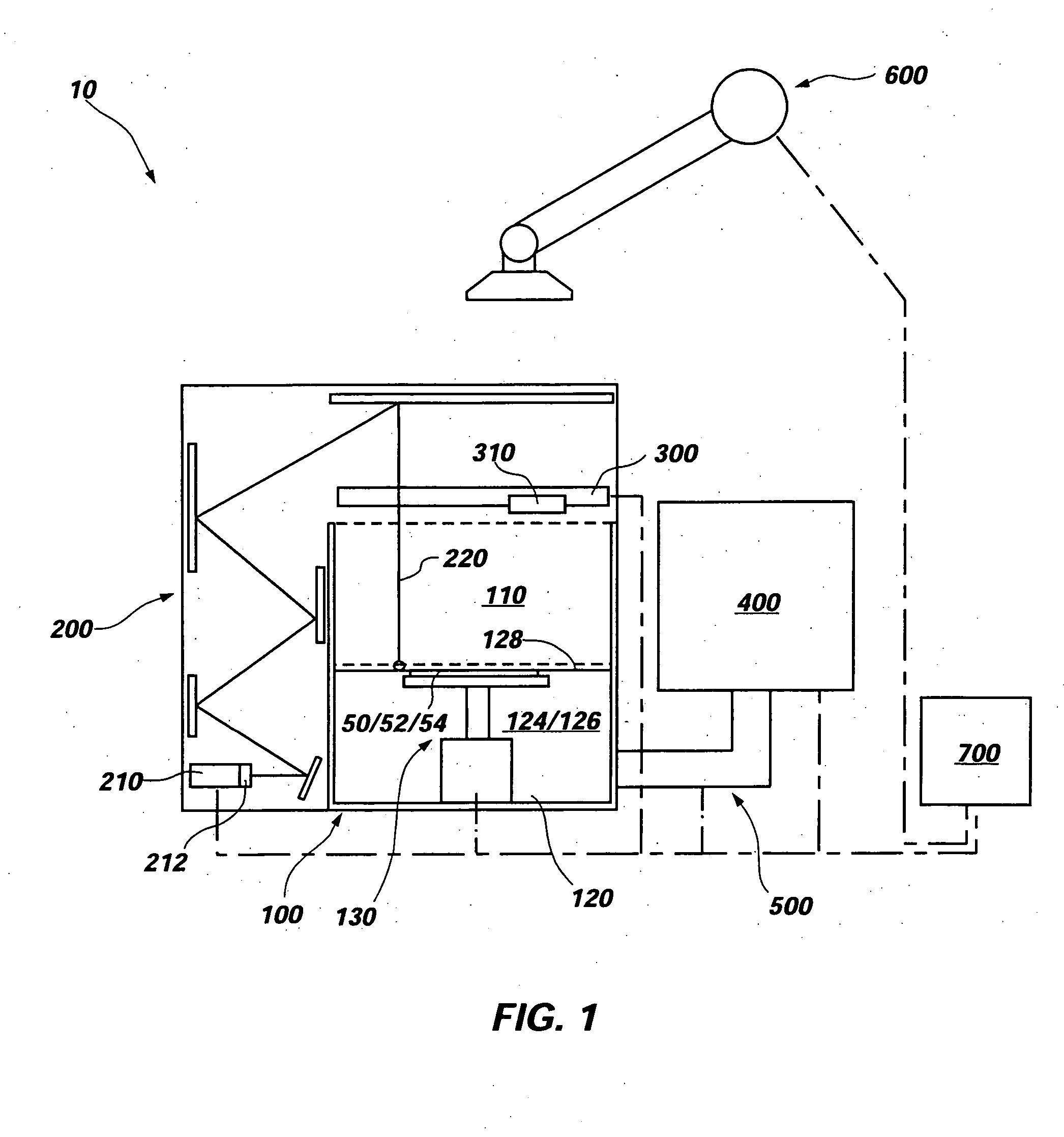
[0017] A programmed material consolidation apparatus, or “stereolithography apparatus” for simplicity, according to the present invention includes a fabrication tank, which is also referred to herein as a “fabrication chamber” or even more broadly as a “fabrication site.”The fabrication tank includes a platen or other support system suitable for carrying substrates upon which structures are to be stereolithographically fabricated, which may also be termed “fabrication substrates.” By way of example only, the fabrication tank and the support therein may be sized and configured to receive one or more semiconductor substrates, each of which carries a plurality of semiconductor devices. Alternatively, or in addition, the platen or other support system may be configured to support freestanding structures as they are fabricated. In addition, the fabrication tank may include a reservoir that is configured to hold a volume of unconsolidated material, such as a liquid polymer.
[0018] A material consolidation system is associated with the fabrication tank in such a way as to direct consolidating energy (e.g., in the form of radiation, such as a laser beam or less-focused radiation) to a surface of the quantity of unconsolidated material within the reservoir of the fabrication tank. When selective consolidation is desired, a high level of precision may be achieved when the consolidating energy is focused and the surface of the quantity of unconsolidated material and the focal point for the consolidating energy substantially intersect one another.

Problems solved by technology

As such, conventional stereolithographic apparatus lack machine vision systems for ensuring that structures are fabricated at certain locations.
Moreover, conventional stereolithographic apparatus lack support systems, handling systems, and cleaning equipment which are suitable for use with relatively delicate structures, such as semiconductor substrates and semiconductor devices that have been fabricated thereon.

Method used


Image

  • Machine vision systems for use with programmable material consolidation apparatus and systems
  • Machine vision systems for use with programmable material consolidation apparatus and systems
  • Machine vision systems for use with programmable material consolidation apparatus and systems

Examples


Embodiment Construction

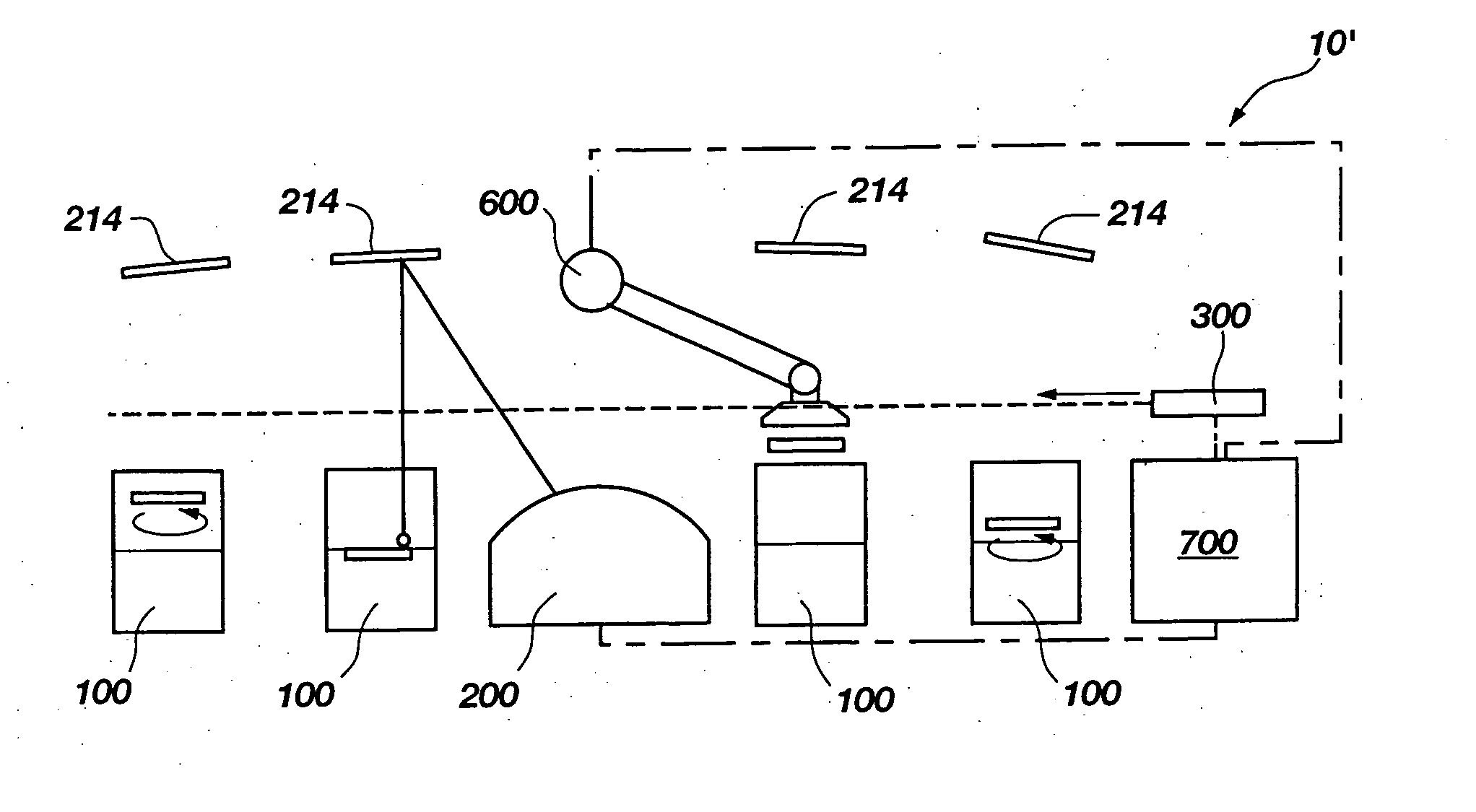
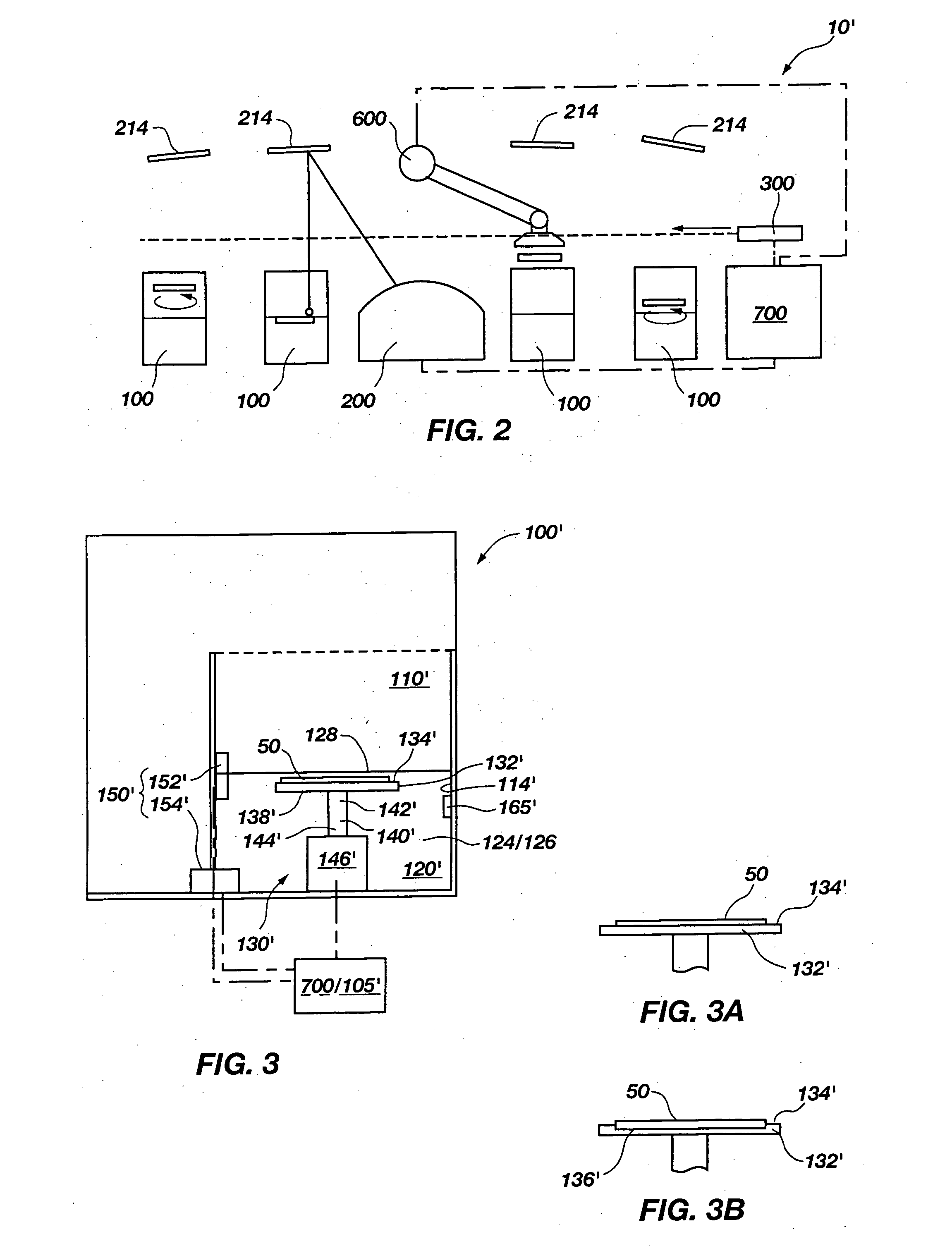
[0053] An exemplary stereolithographic apparatus 10 for fabricating features on semiconductor substrates 52, semiconductor devices 54 or associated components (e.g., lead frames, circuit boards, etc.) (not shown) or other fabrication substrates 50 is schematically depicted in FIG. 1. As shown, stereolithographic apparatus 10 includes a fabrication tank 100 and a material consolidation system 200, a machine vision system 300, a cleaning component 400, and a material reclamation system 500 that are associated with fabrication tank 100. The depicted stereolithographic apparatus 10 also includes a substrate handling system 600, such as a rotary feed system or linear feed system available from Genmark Automation Inc. of Sunnyvale, Calif., for moving fabrication substrates 50 from one system of stereolithographic apparatus to another. Features of one or more of the foregoing systems may be associated with one or more controllers 700, or processing elements, such as computer processors or ...


PUM

PropertyMeasurementUnit
path lengthaaaaaaaaaa
sizeaaaaaaaaaa
pressuresaaaaaaaaaa

Abstract

A programmed material consolidation apparatus includes at least one fabrication site and a material consolidation system associated with the at least one fabrication site. The at least one fabrication site may be configured to receive one or more fabrication substrates, such as semiconductor substrates. A machine vision system with a translatable or locationally fixed camera may be associated with the at least one fabrication site and the material consolidation system. A cleaning component may also be associated with the at least one fabrication site. The cleaning component may share one or more elements with the at least one fabrication site, or may be separate therefrom. The programmed material consolidation apparatus may also include a substrate handling system, which places fabrication substrates at appropriate locations of the programmed material consolidation apparatus.

Description

CROSS-REFERENCE TO RELATED APPLICATION [0001] This application claims the benefit of U.S. Provisional Application No. 60 / 425,567, filed Nov. 11, 2002, the disclosure of which is hereby incorporated in its entirety by this reference.BACKGROUND OF THE INVENTION [0002] 1. Field of the Invention [0003] The present invention relates generally to apparatus for effecting programmed material consolidation techniques, such as stereolithography, and, more particularly, to apparatus that are configured to fabricate features on semiconductor devices and related components. The present invention also relates to programmed material consolidation methods that include use of such apparatus. [0004] 1. Background of Related Art [0005] Over the past decade or so, a manufacturing technique which has become known as “stereolithography” and which is also known as “layered manufacturing” has evolved to a degree where it is employed in many industries. [0006] Basically, stereolithography, as conventionally...

Claims


Application Information

Patent Timeline
Patent Type & Authority Applications(United States)
IPC IPC(8): B29C67/00
CPCB29C67/0096B29C67/0066B29C64/135B29C64/35B33Y30/00B33Y40/00B29C64/357B29C64/188G03F7/0002B33Y50/02
Inventor FARNWORTH, WARREN M.
Owner MICRON TECH INC
Learn More