Organic EL display device and method for manufacturing the same

a technology of organic el and display devices, which is applied in the direction of electroluminescent light sources, thermoelectric devices, electric lighting sources, etc., can solve the problems of difficult to completely shut out water, disadvantageous lowering of the performance of the second electrode, and damage to the organic layer, so as to reduce or prevent the reduction of the sealing performance of the first sealing member, the increase of the cost can be reliably reduced or prevented, and the effect of increasing the productivity of the organic el display

Active Publication Date: 2014-04-29
SHARP KK
View PDF31 Cites 7 Cited by
  • Summary
  • Abstract
  • Description
  • Claims
  • Application Information

AI Technical Summary

Benefits of technology

[0040]According to the present invention, an increase in cost can be reduced or prevented, and a reduction in sealing performance of the first sealing member can be reliably reduced or prevented. Also, the productivity of the organic EL display device can be increased and therefore the yield can be increased.

Problems solved by technology

Here, the organic layer can be damaged by water, and therefore, needs to be shut off from water contained in ambient air.
However, in this organic EL display device, the adhesive material is made of a resin and therefore transmits water contained in ambient air, and therefore, it is difficult to completely shut out water.
Therefore, the second electrode formed on the organic layer is oxidized, so that the performance of the second electrode is disadvantageously lowered.
Therefore, in particular, in the case of a large-size organic EL display device employing glass substrates as the first and second substrates, the glass substrates are warped in the space by their own heavy weight, so that the first and second substrates contact each other, and therefore, the mechanical strength of the organic EL display device is disadvantageously lowered.

Method used


Image

  • Organic EL display device and method for manufacturing the same
  • Organic EL display device and method for manufacturing the same
  • Organic EL display device and method for manufacturing the same

Examples


first embodiment

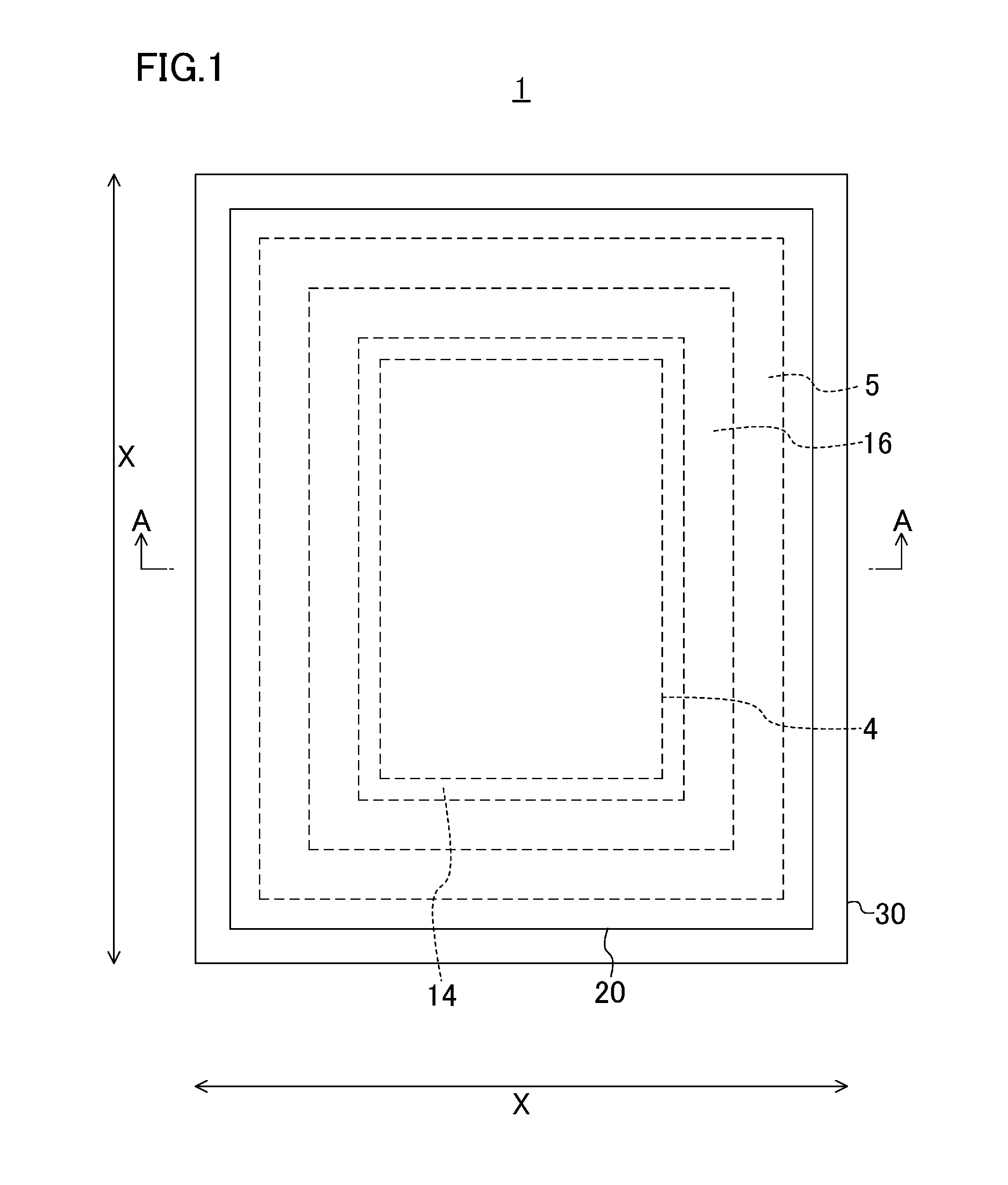
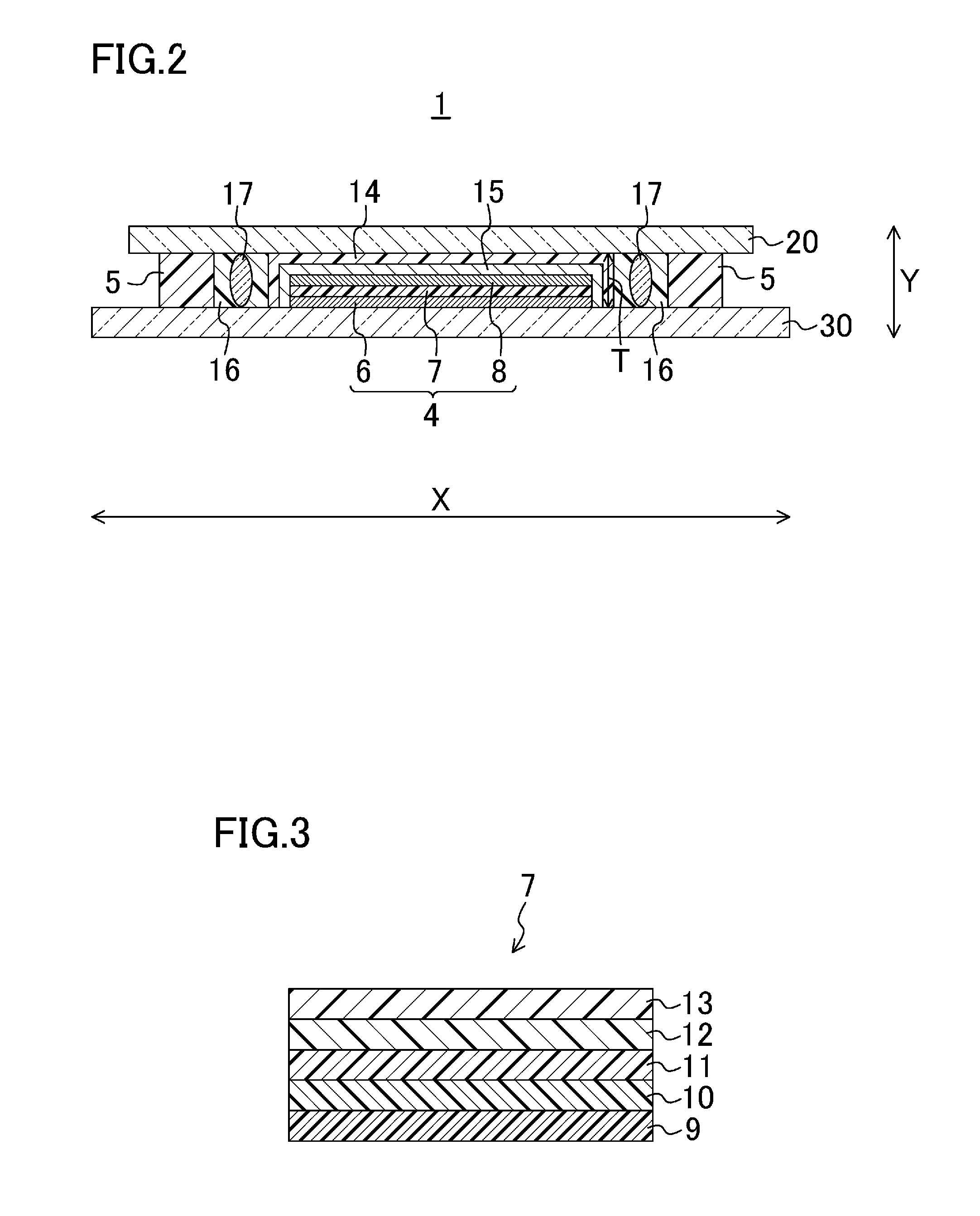
[0065]FIG. 1 is a plan view of an organic EL display device according to a first embodiment of the present invention. FIG. 2 is a cross-sectional view taken along line A-A of FIG. 1. FIG. 3 is a cross-sectional view for describing an organic layer included in an organic EL element provided in organic EL display devices of the embodiments of the present invention.

[0066]As shown in FIGS. 1 and 2, the organic EL display device 1 includes an element substrate 30 (first substrate), a sealing substrate 20 (second substrate) facing the element substrate 30, and an organic EL element 4 which is formed on the element substrate 30 and provided between the element substrate 30 and the sealing substrate 20. The organic EL display device 1 further includes a first sealing member 5 which is used to join (or join by melting (also referred to as “weld”)) the element substrate 30 and the sealing substrate 20 together to seal the organic EL element 4. The first sealing member 5 is formed in the shape...

second embodiment

[0145]Next, a second embodiment of the present invention will be described. FIG. 18 is a plan view of an organic EL display device according to the second embodiment of the present invention. FIG. 19 is a cross-sectional view taken along line B-B of FIG. 18. Note that parts similar to those of the first embodiment are indicated by the same reference characters and will not be described. The organic EL display device is manufactured by a method similar to that described in the first embodiment, and the method will not be described in detail.

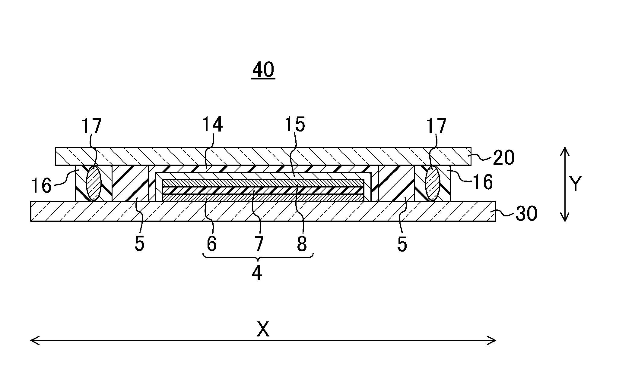
[0146]In the organic EL display device 40 of this embodiment, as shown in FIGS. 18 and 19, the positions of the first sealing member 5 and the second sealing member 16 described in the first embodiment are switched.

[0147]More specifically, as shown in FIGS. 18 and 19, in this embodiment, the second sealing member 16 is provided outside the first sealing member 5 in the plane direction X of the organic EL display device 1. The first sealing member ...

third embodiment

[0152]Next, a third embodiment of the present invention will be described. FIG. 20 is a plan view of an organic EL display device according to the third embodiment of the present invention. FIG. 21 is a cross-sectional view taken along line C-C of FIG. 20. Note that parts similar to those of the first embodiment are indicated by the same reference characters and will not be described. The organic EL display device is manufactured by a method similar to that described in the first embodiment, and the method will not be described in detail.

[0153]In the organic EL display device 50 of this embodiment, as shown in FIGS. 20 and 21, the first sealing member 5 and the second sealing member 16 are separated apart from each other in the plane direction X of the organic EL display device 50 (i.e., a space S is formed between the first sealing member 5 and the second sealing member 16).

[0154]With such a configuration, as described above, even when the first sealing member 5 made of fritted gla...


PUM


Abstract

An organic EL display device (1) includes an element substrate (30), a sealing substrate (20) facing the element substrate (30), an organic EL element (4) provided on the element substrate (30) and between the element substrate (30) and the sealing substrate (20), a first sealing member (5) made of fritted glass and provided between the element substrate (30) and the sealing substrate (20), and configured to weld the element substrate (30) and the sealing substrate (20) to seal the organic EL element (4), a resin member (14) provided between the sealing substrate (20) and the organic EL element (4) and configured to cover a surface of the organic EL element (4), and a second sealing member (16) formed of a resin and provided between the element substrate (30) and the sealing substrate (20).

Description

CROSS REFERENCE TO RELATED APPLICATIONS[0001]This is a U.S. National Phase patent application of PCT / JP2010 / 001465, filed Mar. 3, 2010, which claims priority to Japanese Patent Application No. 2009-140069, filed Jun. 11, 2009, each of which is hereby incorporated by reference in the present disclosure in its entirety.TECHNICAL FIELD[0002]The present invention relates to organic EL display devices including organic electric field light emitting elements (organic electroluminescence elements: hereinafter referred to as “organic EL elements”), and methods for manufacturing the organic EL display devices.BACKGROUND ART[0003]In recent years, organic EL display devices have received attention as a next-generation flat panel display device. The organic EL display device emits light by itself, and has excellent viewing angle characteristics, high visibility, low power consumption, and a small thickness. Therefore, there is an increasing demand for the organic EL display device.[0004]The org...

Claims


Application Information

Patent Timeline
Patent Type & Authority Patents(United States)
IPC IPC(8): H01L29/06
CPCH01L51/525H01L51/5246H01L51/5253H01L51/524H10K59/8723H10K59/873H10K59/8722H10K59/8792H10K59/871H05B33/04H10K50/841H10K50/844H10K50/8426H10K50/8428
Inventor NIBOSHI, MANABUHIRASE, TAKESHIKOBAYASHI, YUHKI
Owner SHARP KK
Why Eureka
Try Eureka