Connecting member of electrical circuit

a technology of connecting member and electrical circuit, which is applied in the direction of fixed connection, high current circuit adaptation, and incorporation of printed electric components, etc. it can solve the problems of inability to use printed circuit boards up to rated current, inapplicability, and inability to increase the thickness of copper foil, so as to reduce or prevent the increase in cost, increase the thickness or width of copper foil, and increase the size of printed circuit boards

Active Publication Date: 2015-05-19
DAIKIN IND LTD
View PDF26 Cites 6 Cited by
  • Summary
  • Abstract
  • Description
  • Claims
  • Application Information

AI Technical Summary

Benefits of technology

[0050]According to the present invention, the terminal connecting section (11, 21, 31) of the connecting member (10, 20, 30) is connected to the terminal pins (3a) of the power-supply circuit element (3) such as the power module (3), and the electrical wire (8) is attached to the wire connecting section (12, 22, 32) of the connecting member (10, 20, 30). Current supplied from the power-supply circuit element (3) is supplied to the target to be driven through the connecting member (10, 20, 30) and the electrical wire (8), thereby not applying current of the main power-supply circuit to the wiring pattern (copper foil) of the printed circuit board (2). Thus, it is not necessary to increase the thickness or width of the copper foil of the printed circuit board (2), and to provide the heat dissipating fin on the wiring pattern. Consequently, the high-current rating can be realized without increasing the size of the printed circuit board unit, and the increase in cost can be reduced or prevented. In addition, thick material is used for the connecting member, thereby reducing the increase in temperature. With entirely-improved heat transfer, the printed circuit board unit can be used up to the limit of current which can be applied to a chip packaged in the power module. In the present invention, a specific shape of the connecting member can be set as required.
[0056]According to the seventh aspect of the invention, the leg sections (14) configuring the wire connecting section (12) of the terminal base are fixed with the leg sections (14) standing on the printed circuit board (2), and the seat plate (13) is positioned above the leg sections (14). The most part of the wire connecting section (12) does not contact the printed circuit board (2). Thus, even if heat is generated by applying current to the terminal base, heat can be efficiently dissipated from the wire connecting section (12). In addition, the terminal connecting section (11) is formed by bending the member relative to the leg section (14), and therefore the terminal connecting section (11) can be easily formed in the connecting member having the shape of the terminal base.
[0060]According to the tenth aspect of the invention, the fixing tips (14b) are inserted into the attachment holes (2b) in order to attach the wire connecting section (12) to the printed circuit board (2). In such a state, since the base end section of the fixing tip (14b) has the larger diameter than that of the tip end section of the fixing tip (14b), the fixing tip (14b) is inserted into the attachment hole (2b) up to its base end, resulting in secure installation of the wire connecting section (12). Thus, the wire connecting section (12) can be positioned on the printed circuit board (2), and a pullout of the wire connecting section (12) can be reduced or prevented.
[0021]In the fourth aspect of the invention, the terminal pins (3a) of the circuit element (3) are bonded to the terminal connecting section (11, 21, 31) arranged in parallel to the printed circuit board (2) outside the hole (2c) formed in the printed circuit board (2), and the electrical wire (8) is connected to the wire connecting section (12, 22, 32). Then, current from the circuit element (3) flows into the electrical wire (8) through the connecting member. The terminal connecting section (11) provided in the connecting member may be formed so as to be parallel to the printed circuit board (2) in any position.
[0057]According to the eighth aspect of the invention, the bent section (14a) is sloped, and therefore the bent section (14a) protrudes from the printed circuit board (2) when arranging the terminal connecting section (11) inside the hole (2c) formed in the printed circuit board (2). Thus, heat can be efficiently dissipated by the bent section (14a).
[0058]In addition, in such an aspect of the invention, the non-soldered space (10s) specified in the eleventh aspect of the invention is not required, the conductor width extending from the terminal connecting section (11) to the bent section (14a) can be broader. Thus, heat generation is reduced, and heat is well dissipated. In addition, higher current can be applied.
[0054]According to the fifth aspect of the invention, the terminal pins (3a) of the circuit element (3) such as the power module (3) are bonded to the terminal connecting section (11, 21, 31) of the connecting member by soldering, thereby reducing the size of a bonding section as compared to, e.g., a case where the terminal pins (3a) are bonded by using screws. Thus, the whole size of the printed circuit board unit can be reduced. In addition, the terminal pins are soldered to the connecting member, thereby decreasing electrical resistance, and reducing the increase in temperature even when applying high current.
[0032]A tenth aspect of the invention is intended for the connecting member of the ninth aspect of the invention, in which the fixing tip (14b) is formed so as to have a length which allows the fixing tip (14b) to penetrate the attachment hole (2b) and to protrude from the printed circuit board (2); a base end section engaged with the attachment hole (2b) is formed so as to have a larger diameter than that of a tip end section protruding from the attachment hole (2b); and the base end section is pressed and fitted into the attachment hole (2b).
[0067]According to the eighteenth aspect of the invention, the connecting member has a two-piece structure. The terminal connecting section (21) of the first member (20a) is connected to the terminal pins (3a) of the power-supply circuit element (3) such as the power module (3), and the electrical wire (8) is connected to the wire connecting section (22) of the first member (20a). Further, the second member (20b) supporting the first member (20a) is attached to the printed circuit board (2). Current supplied from the power-supply circuit element (3) such as the power module (3) is supplied to the target to be driven through the first member (20a) and the electrical wire (8). Thus, current of the main power-supply circuit does not flow through the wiring pattern (copper foil) of the printed circuit board (2). It is not necessary to increase the thickness or width of the copper foil of the printed circuit board (2), and to provide the heat dissipating fin (11b) on the wiring pattern. Consequently, the high-current rating can be realized without increasing the size of the printed circuit board unit, and the increase in cost can be reduced or prevented.

Problems solved by technology

Thus, the printed circuit board cannot be used up to rated current.
However, in order to lower the resistance value, it is necessary to expand the width of the copper foil because the thickness of the copper foil cannot be extremely increased.
Thus, it is not practical that, in the printed circuit board unit using the high-current power module having the narrower space between the terminal pins, the width of the copper foil is expanded in order to apply high current.

Method used


Image

  • Connecting member of electrical circuit
  • Connecting member of electrical circuit
  • Connecting member of electrical circuit

Examples


first embodiment

of the Invention

[0092]A first embodiment of the invention will be described. The first embodiment relates to a printed circuit board unit used for a control device of a refrigeration apparatus (air conditioning apparatus).

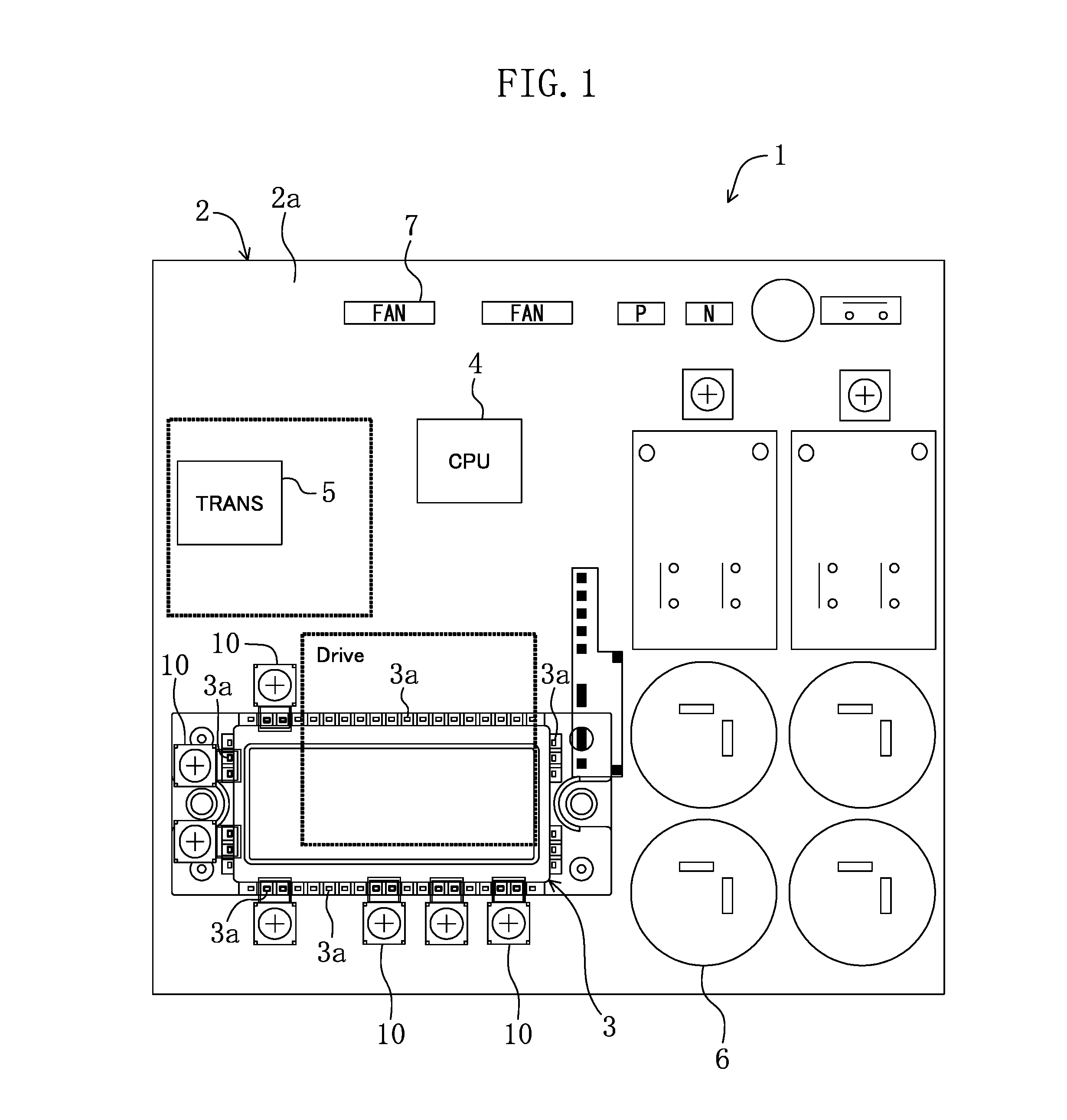
[0093]FIG. 1 is a plan view of a printed circuit board unit (1). The printed circuit board unit (1) is configured by mounting a power-supply circuit element such as a power module (inverter module to be connected to an external power supply) (3) and other electronic components (4, 5, 6, 7) on a printed circuit board (2). Since the power module (3) is positioned on the back side of the printed circuit board (2) as viewed in the figure, there are parts which should be actually indicated by a dashed line. However, for the sake of simplicity, such parts are indicated by a solid line in the figure. The electronic components (4, 5, 6, 7) of the printed circuit board (2) includes, e.g., a CPU (central processing unit) (4), a transformer (5), capacitors (6), and connectors...

second embodiment

of the Invention

[0143]A second embodiment of the present invention will be described.

[0144]The second embodiment illustrated in FIGS. 12(A) and 12(B) has a two-piece structure of a terminal base (connecting member). FIG. 12(A) is a cross-sectional view of a main section with the terminal base being connected, and FIG. 12(B) is a plan view.

[0145]A terminal base (20) specifically includes a first member (20a) with a terminal connecting section (21) and a wire connecting section (22); and a second member (20b) supporting the first member (20a), and attached to a printed circuit board (2).

[0146]The first member (20a) is formed by bending flat-bar-like conductive metal material having a constant width. The first member (20a) includes the wire connecting section (22) to be mounted on and fixed to the second member (20b); a connecting section (25) downwardly extending from one end of the wire connecting section (22) at 90°; and the terminal connecting section (21) extending from a lower en...

third embodiment

of the Invention

[0163]A third embodiment of the present invention, which is illustrated in FIGS. 14(A) and 14(B) will be described. FIG. 14(A) is a cross-sectional view of a main section, which illustrates a connection state in the present embodiment, and FIG. 14(B) is a plan view.

[0164]The third embodiment is an example in which an approximately flat terminal plate (30) is used as a connecting member for connecting a circuit element (power module) of an electrical circuit including a printed circuit board (2), to an electrical wire (8).

[0165]The terminal plate (30) is formed by pressing flat-bar-like conductive metal material having constant width. The terminal plate (30) includes, at one end, a terminal connecting section (31) to be directly connected to terminal pins (3a) of the circuit element such as a power module (3); and, at the other end, a wire connecting section (32) to be connected to the electrical wire (8). The terminal connecting section (31) and the wire connecting s...


PUM


Abstract

A connecting member such as a terminal base is used in connection with a printed circuit board unit in which circuit elements such as a power module are mounted on a printed circuit board. The connecting member connects the circuit element of an electrical circuit including the printed circuit board, to an electrical wire. The connecting member includes a terminal connecting section to be directly connected to terminal pins of the circuit element; a wire connecting section to be connected to the electrical wire; and attachment sections for attaching the connecting member to the printed circuit board.

Description

TECHNICAL FIELD[0001]The present invention relates to a connecting member of an electrical circuit, which is used for connecting a circuit element of the electrical circuit including a printed circuit board, to an electrical wire.BACKGROUND ART[0002]Generally, when mounting a power-supply circuit element such as a power module (a power module will be described below as a representative example of power-supply circuit elements) on the printed circuit board in a printed circuit board unit, terminal pins of the power module are bonded to printed wire (copper foil) of a main circuit on the printed circuit board. An inverter module is used as a power module in, e.g., a refrigeration apparatus (the refrigeration apparatus described herein includes an air conditioning apparatus), and such a power module is connected between an external power supply and an inverter compressor (target to be driven). In such a configuration, current supplied through terminal pins of the power module flows thr...

Claims


Application Information

Patent Timeline
Patent Type & Authority Patents(United States)
IPC IPC(8): H05K1/16H05K1/09H05K1/11H01R4/34H01R12/51H05K1/02H05K3/32
CPCH05K1/0263H05K3/32H01R12/515H01R4/34H05K2201/10287H05K2201/10295H05K2201/10409H05K2201/10545H05K2201/10962
Inventor KAGIMURA, SUMIODOUMAE, HIROSHIDOI, HIROTAKAGENDA, SHUUJI
Owner DAIKIN IND LTD
Why Eureka
Try Eureka