Uplink interference mitigation method and apparatus

a technology of uplink interference and mitigation method, which is applied in the direction of electrical equipment, wireless communication services, wireless communication, etc., can solve the problems of difficult to efficiently mitigate the sector interference for the duration of uplink, the interference may occur in neighboring sectors, and the time is required to be long. , to achieve the effect of reducing the time required for uplink interference, and reducing the time required

Active Publication Date: 2014-04-29
WIRELESS ALLIANCE LLC
View PDF9 Cites 2 Cited by
  • Summary
  • Abstract
  • Description
  • Claims
  • Application Information

AI Technical Summary

Benefits of technology

[0028]The method and apparatus for mitigating uplink interference according to the present invention enables to mitigate the UL interference.
[0029]Also, the subchannel allocation may be dynamically changed to mitigate the UL interference.

Problems solved by technology

However, as shown in FIG. 1, if the data burst is allocated to all the subchannels in each sector for the uplink duration, interference may occur by the neighboring sectors.
That is, if the aforementioned set information is changed, considerable time is needed until the changed set information is applied to each mobile station.
Eventually, it is difficult to efficiently mitigate the sector interference for the uplink duration.

Method used


Image

  • Uplink interference mitigation method and apparatus
  • Uplink interference mitigation method and apparatus
  • Uplink interference mitigation method and apparatus

Examples


Embodiment Construction

[0037]Reference will now be made in detail to the preferred embodiments of the present invention, examples of which are illustrated in the accompanying drawings.

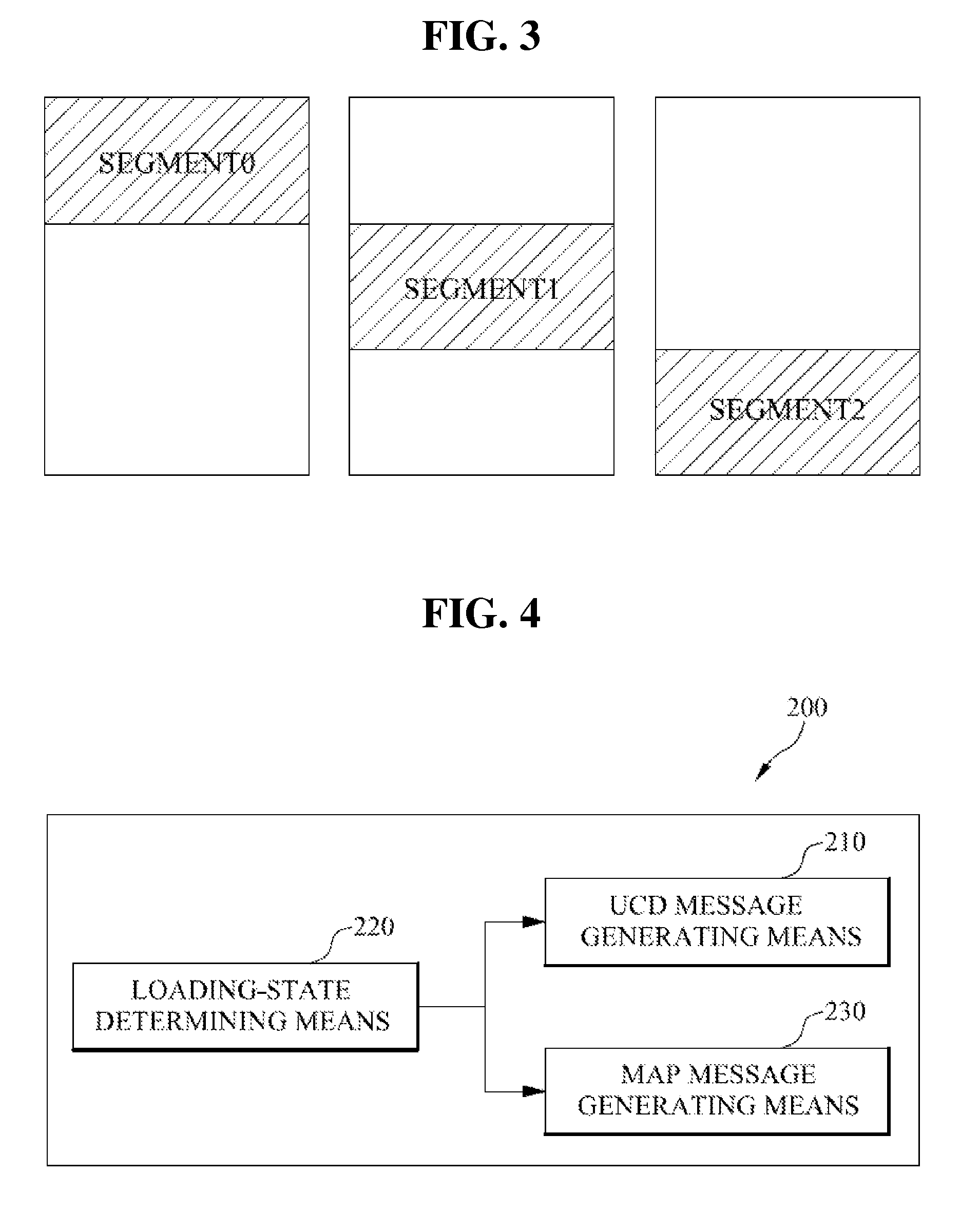
[0038]FIG. 4 is a block diagram illustrating an uplink interference according mitigation apparatus to one embodiment of the present invention. As shown in FIG. 4, the uplink interference mitigation apparatus 200 includes a UL channel descriptor (hereinafter, referred to as ‘UCD’) message generating means 210, a loading-status determining means 220, and a map message preparing means 230.

[0039]The UCD message generating means 210 generates a UCD message to be allocated to a UCD region, wherein the UCD message defines a region to be allocated with a data burst for an uplink duration.

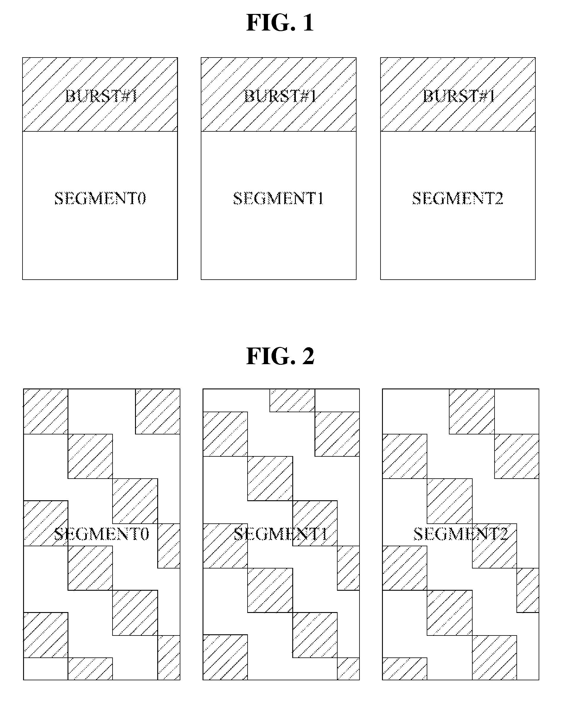
[0040]The UCD message generating means 210 according to one embodiment of the present invention may create the UCD message to define all or some of subchannels for the uplink duration as the data burst allocation region.

[0041]According to one embodi...


PUM


Abstract

Disclosed is a method and apparatus for mitigating uplink interference in the wireless communication system, wherein the method comprises determining a loading-status value for each sector; if the loading-status value is not greater than the first threshold value, generating UL zone switch IE and UL allocation start IE to allocate data bursts of the sectors to different subchannels; and preparing an uplink map using the UL zone switch IE and UL allocation start IE for each sector, wherein the uplink duration indicates a duration where all the subchannels are used for allocation of the data burst.

Description

BACKGROUND[0001]1. Field of the Invention[0002]The present invention relates to a wireless communication system, and more particularly, to a method and apparatus for mitigating uplink interference in the wireless communication system.[0003]2. Discussion of the Related Art[0004]Based on a proposed standard of IEEE (Institute of Electrical and Electronics Engineers) 802.16, BWA (Broadband Wireless Access) supporting OFDMA (Orthogonal Frequency Division Multiplexing Access) allows to transmit much information in a short time owing to a broadband frequency, wherein the frequency in one frequency band is divided and is then efficiently used by plural users.[0005]This wireless communication system one-dimensionally allocates data bursts for an uplink duration except a predetermined region in a symbol (time)-first order. That is, if the data burst allocation is completed for all subchannels in a certain symbol, the data burst allocation is started for the subchannels in the next symbols. T...

Claims


Application Information

Patent Timeline
Patent Type & Authority Patents(United States)
IPC IPC(8): H04W4/00
CPCH04W72/082H04W36/20H04W72/1252H04W72/541H04W72/52H04W72/21
Inventor JEON, HYUNG, JOON
Owner WIRELESS ALLIANCE LLC
Why Eureka
Try Eureka