

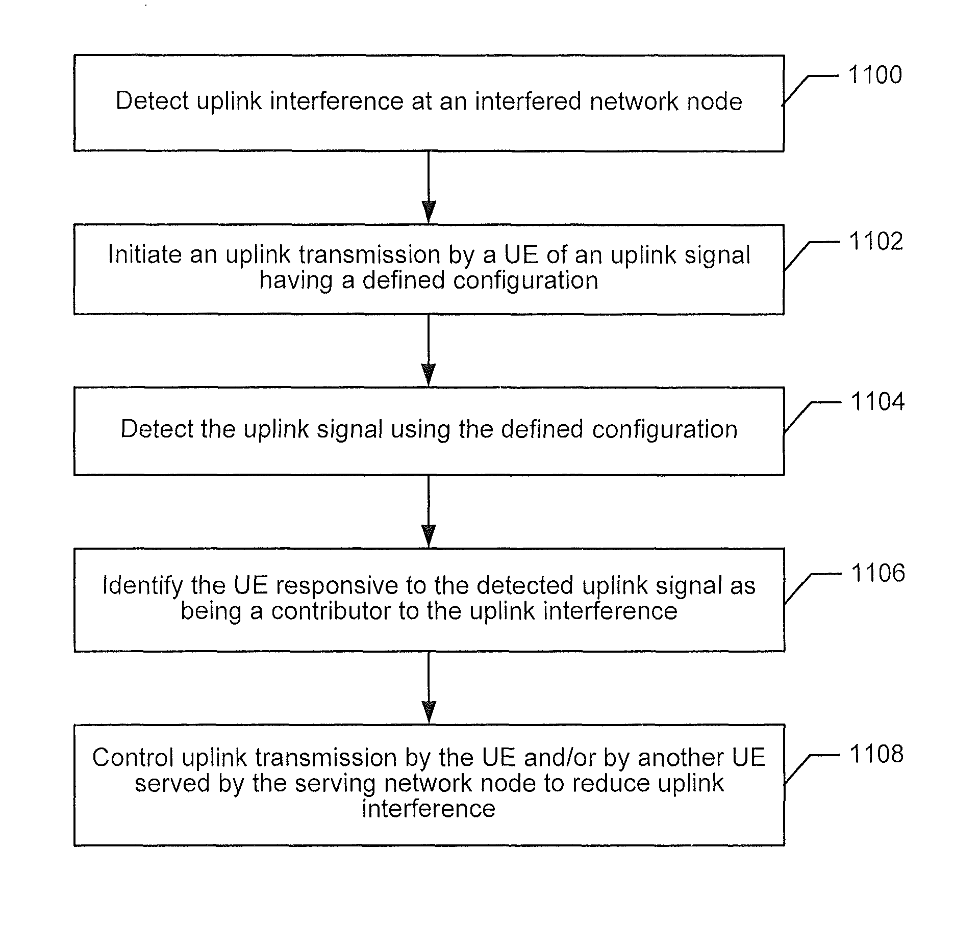
Generating uplink signals from user equipment nodes to identify interferers to a network node
a technology of user equipment and uplink signals, applied in the field of wireless communication systems, can solve the problems of not always being able to identify the interference relationship, femto base station may induce significant downlink interference to the ue, and high interference to the femto base station cell, so as to reduce uplink interference
- Summary
- Abstract
- Description
- Claims
- Application Information
AI Technical Summary
Benefits of technology
Problems solved by technology
Method used
Image

Examples
Embodiment Construction
[0056]In the following detailed description, numerous specific details are set forth in order to provide a thorough understanding of the invention. However, it will be understood by those skilled in the art that the present invention may be practiced without these specific details. In other instances, well-known methods, procedures, components and circuits have not been described in detail so as not to obscure the present invention.
[0057]The following example embodiments provide a number of advantages and benefits relative to existing systems and methods for managing uplink interference by a UE to a network node. It will be appreciated by those skilled in the art in view of the present description, however, that the invention is not limited to these embodiments which produce any or all of these advantages or benefits and that other advantages and benefits may be realized depending upon the particular implementation.
[0058]Various embodiments of the present invention are directed to u...
PUM
 Abstract
Description
Claims
Application Information