Dynamic stability control systems and methods for industrial lift trucks

a technology of dynamic stability control and industrial lift trucks, which is applied in the direction of rotary clutches, fluid couplings, instruments, etc., can solve the problems of uneven floor surfaces, periodic vibration that can be transmitted throughout the frame of the truck, and the impact of force may still be negative, so as to reduce or eliminate the effect of truck movemen

Active Publication Date: 2014-05-20
RAYMOND LTD
View PDF107 Cites 26 Cited by
  • Summary
  • Abstract
  • Description
  • Claims
  • Application Information

AI Technical Summary

Benefits of technology

[0018]The present invention overcomes the drawbacks of the previous lift truck systems and methods by providing additional stability control features to reduce or eliminate motion of the truck in one or more of the X-axis, Y-axis, and Z-axis. Some embodiments may include, alone or in combination with the stability control, vibration control to further stabilize the motion of the truck.
[0019]In one aspect, the present invention provides a system for stabilizing a lift truck. The system comprises at least one caster to provide lift truck stability. A sensor provides a value of motion of the lift truck in at least one of an X-axis and a Y-axis. A control system is included to determine which direction the lift truck is moving in the at least one of the X-axis and the Y-axis by comparing the value of motion to a stationary value of motion. The control system also compares the value of motion to a threshold value of motion. An actuator locks movement of the caster on a side of the lift truck based on the direction that the control system determined the lift truck to be moving.

Problems solved by technology

A lift truck traveling throughout a facility may encounter debris on the floor and uneven floor surfaces.
These can take the form of expansion joints, cracks in the floor surface or man-made objects such as ramps going between buildings or into tractor trailers.
Tire irregularities and / or the floor can also cause periodic vibration that can be transmitted throughout the frame of the truck.
If there is no operator, such as when the truck is being remotely controlled, the resultant forces may still have negative effects because equipment 18 on the truck may be rendered less effective.
The sudden movement caused by the floor condition can diminish the effectiveness and / or accuracy of the sensory equipment and may necessitate that the truck be operated at slower speeds to reduce the effects of the floor conditions.
Slower operating speeds may equate to an undesirable reduction in overall equipment productivity.
Without the flexible spring loaded casters and the ability to adjust the casters with shims, the casters may end up carrying most of the weight and the traction wheel may slip due to not enough contact force, or the traction wheel may take most of the weight, causing the truck to slightly tilt to one caster or the other.
Caster adjustment may be time consuming, and may include jacking up the truck, estimating how big a shim to install, and then seeing if the shim was too big or too little.
Conversely, the operator may sense rough floor conditions and objects on the floor, or cracks in the floor may effect the truck as the caster rolls over them.
Nevertheless, when one caster hits a large bump on the floor, the damper responds to the high speed motion of the caster by generating considerable force and may tilt the truck because the damper force is a function of caster motion, not truck roll.
So, in some cases, the torsion bar may actually induce a tilt in the truck.
On rough floors, operators of a truck with this configuration are known to feel oscillations and the truck may tilt on most every bump.
Also, the effect of hitting an object with one caster may cause a significant contact and tilt.
The prior methods suffer from not monitoring the orientation of the truck in one or more of the three axis of motion.
At best, the prior methods only improve the tradeoff between soft springs and the truck rolling versus hard springs and truck dampers that limit the performance of the spring only caster configurations.
Another disadvantage of these previously used methods has been that the force or motion created is fixed.

Method used


Image

  • Dynamic stability control systems and methods for industrial lift trucks
  • Dynamic stability control systems and methods for industrial lift trucks
  • Dynamic stability control systems and methods for industrial lift trucks

Examples


Embodiment Construction

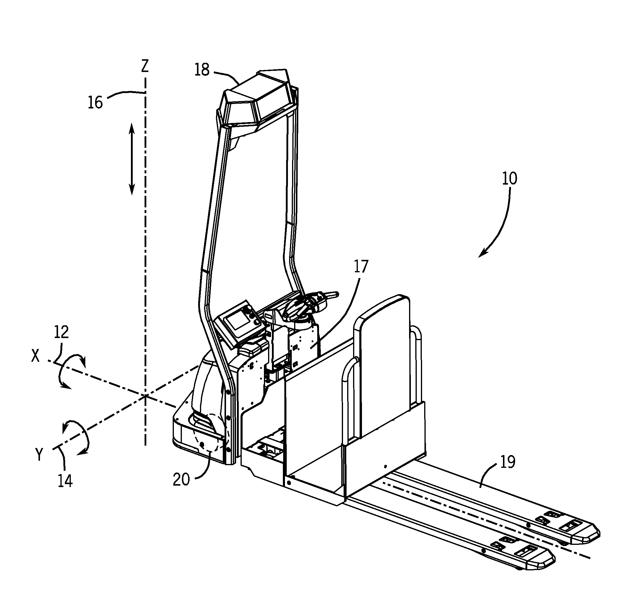
[0030]The various aspects of the invention will be described in connection with improved stability and vibration control of industrial lift trucks. That is because the features and advantages that arise due to embodiments of the invention are well suited to this purpose. Still, it should be appreciated that the various aspects of the invention can be applied to achieve other objectives as well.

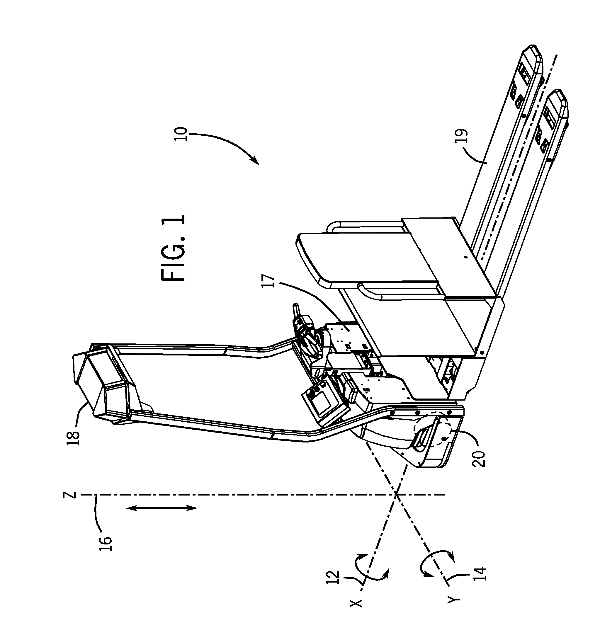
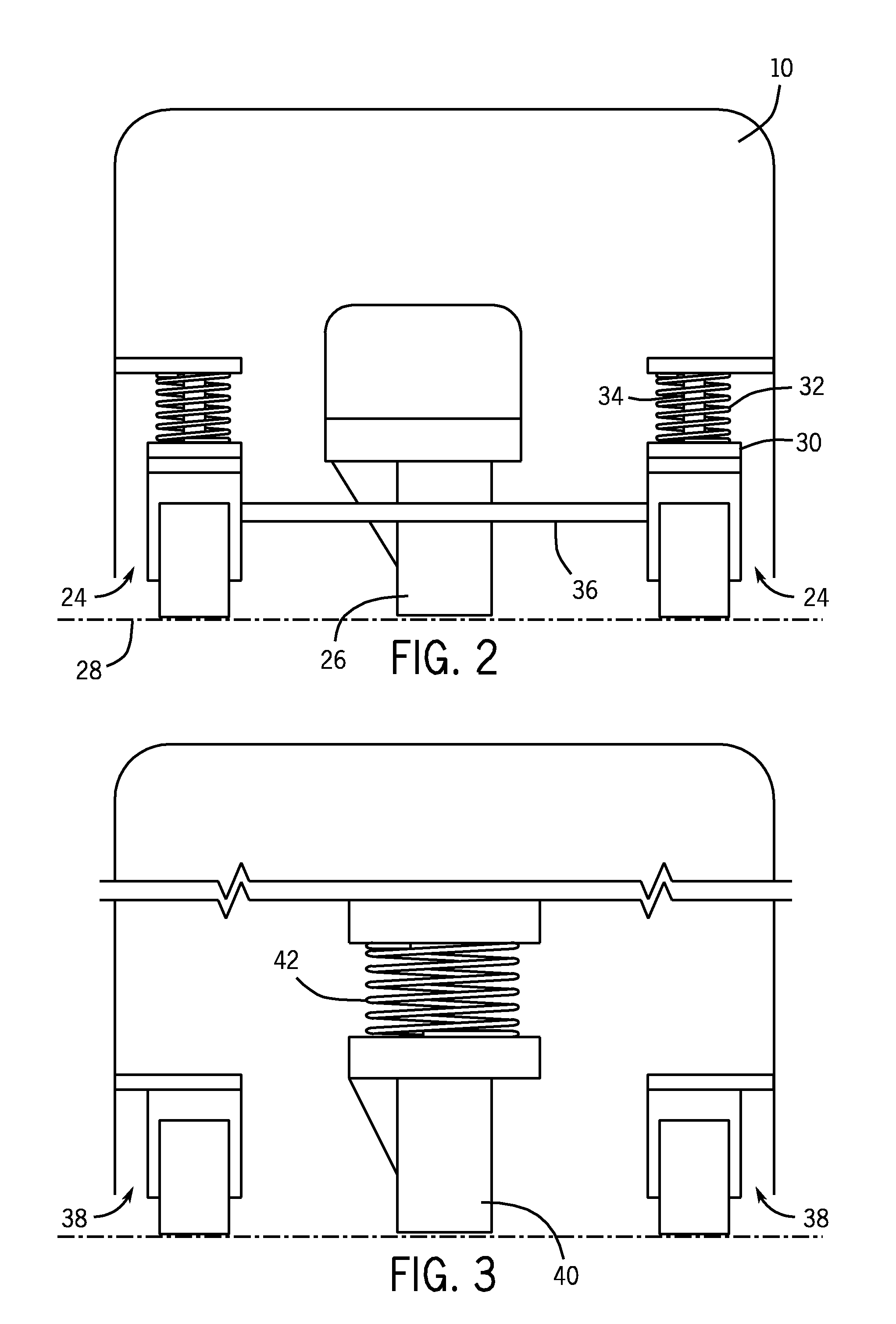
[0031]Embodiments of the invention described herein, either alone or in combination, are well suited to provide a dynamically stabilized lift truck, including, for example, a dual-purpose fork lift truck that may be operated as an automated robotic vehicle and also as a standard manually operated truck. The truck achieves stabilization through one or more individual or combined improvements that are configured to effect motion in any one of three axes, and in some embodiments, plus reduce vibration. The collective improvements provide protection for sensitive electronic components, increase op...


PUM


Abstract

A lift truck includes systems and methods for improved stability control. Stability control features reduce or eliminate motion of the truck in one or more of the X-axis, Y-axis, and Z-axis. Some embodiments may include, alone or in combination with the stability control, vibration control to further stabilize the motion of the truck.

Description

CROSS-REFERENCE TO RELATED APPLICATIONS[0001]This application claims the benefit of U.S. Provisional Patent Application Ser. No. 61 / 454,188, filed Mar. 18, 2011, and entitled “Dynamic Stability Control Systems And Methods For Industrial Lift Trucks,” which is hereby incorporated by reference.STATEMENT CONCERNING FEDERALLY SPONSORED RESEARCH OR DEVELOPMENT[0002]Not applicable.FIELD OF THE INVENTION[0003]The present invention relates to the field of industrial lift trucks, and more specifically to systems and methods for improved stability control for lift trucks.BACKGROUND OF THE INVENTION[0004]Lift trucks are designed in a variety of configurations to perform a variety of tasks. A lift truck traveling throughout a facility may encounter debris on the floor and uneven floor surfaces. These can take the form of expansion joints, cracks in the floor surface or man-made objects such as ramps going between buildings or into tractor trailers. Tire irregularities and / or the floor can also ...

Claims


Application Information

Patent Timeline
Patent Type & Authority Patents(United States)
IPC IPC(8): G06F7/70G06F19/00
CPCB60G17/016B62B5/0006B66F9/24B62B3/0612B60G17/017B66F9/07586B60G2800/91B62B5/0069B60G2204/46B62B2301/00B66F9/07559B60G2600/02B60G2300/022
Inventor MCCABE, PAUL P.KIRK, JOHN B.GREGORY, BRYCEFIELD, MICHAEL G.
Owner RAYMOND LTD
Why Eureka
Try Eureka