Integrated Ligament Strain Measurement

a technology of integrated ligaments and strains, applied in the field of medical/surgical devices, systems and methods, can solve the problems that existing techniques often don't correlate with the patient body's own sensing mechanism, and achieve the effects of reducing wear, increasing durability, and increasing functional performan

Active Publication Date: 2019-07-11
SURGICAL SENSORS BVBA
View PDF5 Cites 3 Cited by
  • Summary
  • Abstract
  • Description
  • Claims
  • Application Information

AI Technical Summary

Benefits of technology

[0012]The present invention serves to increase functional performance (e.g., biomechanical function), increase durability (e.g., reduced wear), reduce or eliminate abnormal motion (e.g., paradoxical motion), and create a more natural postoperative feeling (e.g., improved proprioception) for said individual patient. By interpreting and understanding the pre-operative strain measurements of a patient's knee or other joint and comparing these to intra-operative strain values measured during operation, a surgeon may improve the overall result of the operation iteratively. Overall, the surgeon needs to take into account th

Problems solved by technology

Furthermore, existing techniques often don't correlate with t

Method used


Image

  • Integrated Ligament Strain Measurement
  • Integrated Ligament Strain Measurement
  • Integrated Ligament Strain Measurement

Examples


first embodiment

Example 1: First Embodiment According to the Present Invention

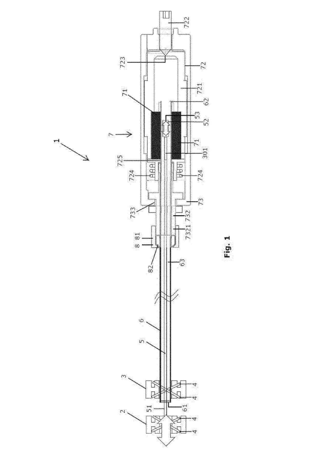
[0220]FIG. 1 shows a first embodiment according to the present invention. Particularly, the figure shows a device 1 suitable for measuring the difference between a strain in a ligament at a first point in time and said strain at a second point in time. A first ligament-retaining element 2 and a second ligament-retaining element 3 have a shape and dimensions suitable for being fastened on said ligament close to each other.

[0221]Specifically, FIG. 1 shows the front of said first ligament-retaining element. Said first ligament-retaining element has a front width of about 4 mm along a width direction essentially parallel to the wire. Said first ligament-retaining element has a front height of about 10 mm along a height direction essentially perpendicular to said width direction. Said first ligament-retaining element has a depth of about 2 mm along a depth direction (not shown on FIG. 1) essentially perpendicular to said width...

second embodiment

Example 2: Second Embodiment According to the Present Invention

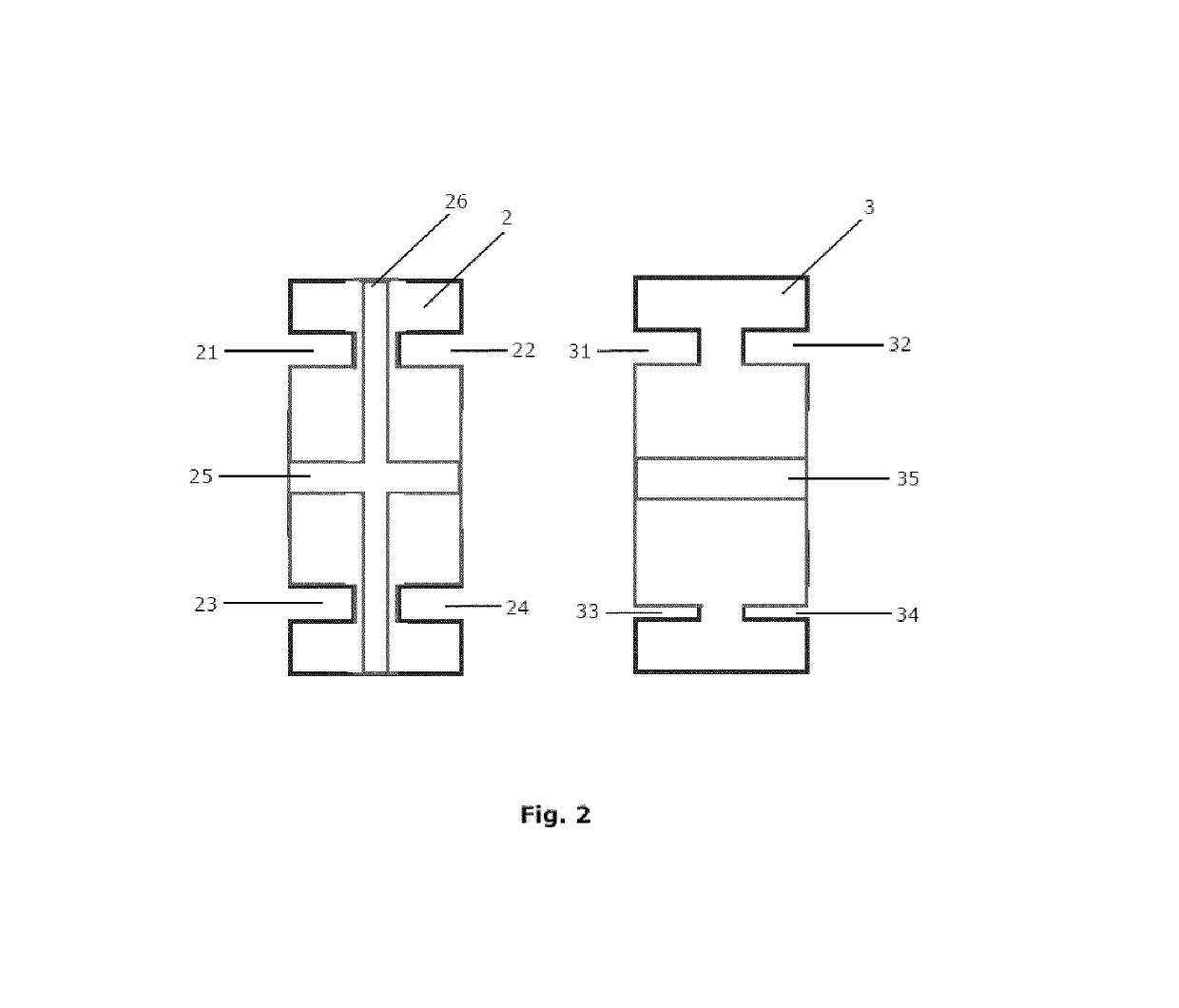
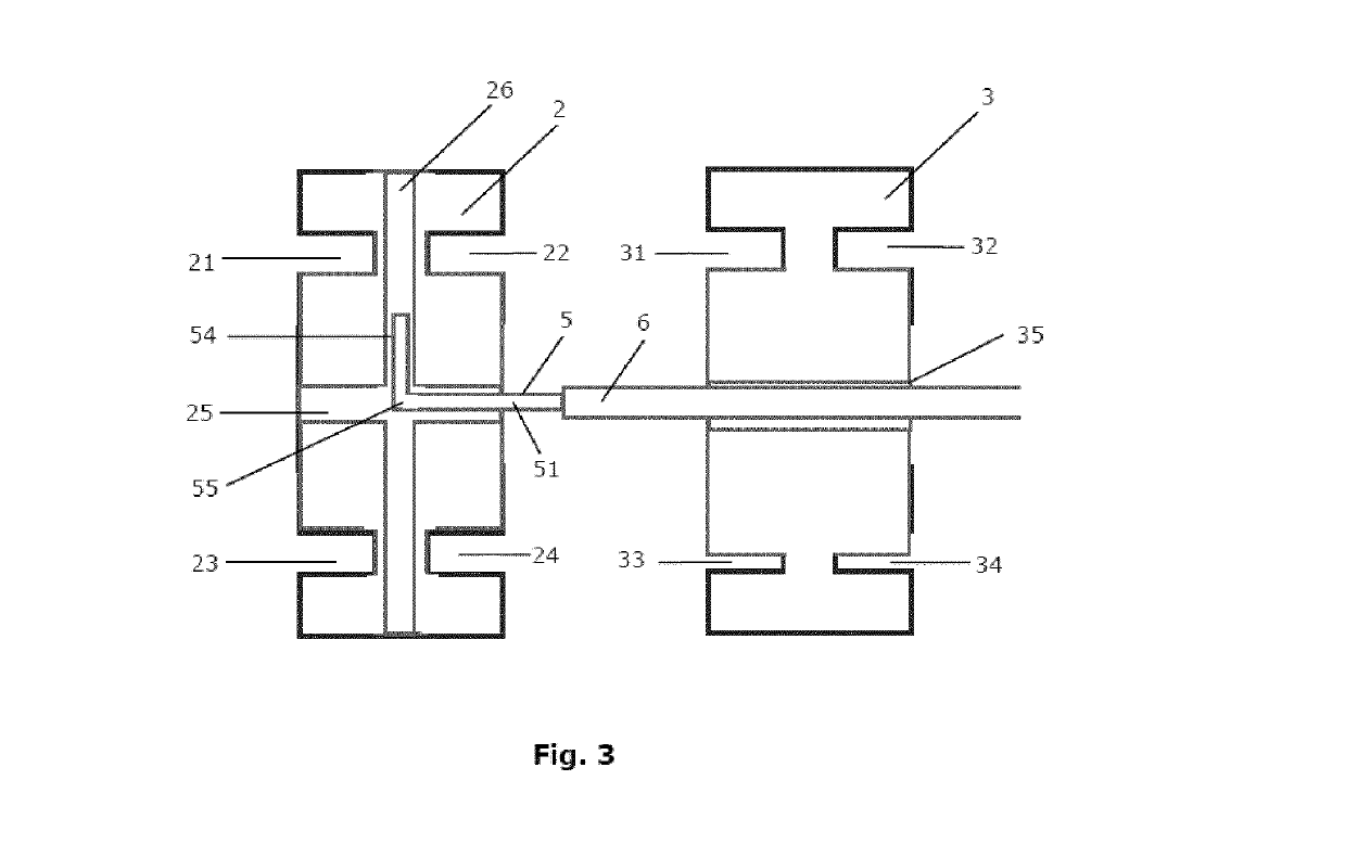
[0230]The second embodiment according to the present invention is illustrated in FIGS. 2 and 3. Both figures show a second embodiment of said first and second ligament-retaining element 2 and 3, respectively. Similar as in the first embodiment, to facilitate gluing of the outer end of said distal wire portion 51 to said first ligament-retaining element 2, said first ligament-retaining element 2 comprises a first groove 25 along a width direction.

[0231]Similar as in the first embodiment, to facilitate gluing of said distal end 61 to said second ligament-retaining element 3, said second ligament-retaining element 3 comprises a second groove 35 along said width direction. In an alternative embodiment (not shown in the figures), the second ligament-retaining element does not comprise a second groove 35 but instead a hole to facilitate gluing of said distal end 61 to said second ligament-retaining element 3. Hereby, said hole...

third embodiment

Example 3: Third Embodiment According to the Present Invention

[0234]The third embodiment according to the present invention is illustrated in FIGS. 4 and 5. It shows the same inner housing 72 and outer housing 73 as in the first embodiment, yet disassembled instead of assembled.


PUM


Abstract

The current invention relates to an integrated device suitable for measuring the difference between a strain in a ligament at a first point in time and said strain at a second point in time, said integrated device comprising: a ligament-attaching element adapted to be fastened on said ligament; a slider module adapted to be fastened on said ligament near said first ligament-attaching element, said slider module comprising a slider guiding channel; a slider comprising a distal slider end and a proximal slider end, said distal slider end fastened on said ligament-attaching element, said proximal slider end guided in said slider guiding channel; a sensor configured to measure a strain-indicating parameter representing a position of said proximal slider end for obtaining said difference between said strain in said ligament at said first point in time and said strain at said second point in time, wherein said sensor comprises a Hall sensor which converts a position of said proximal slider end into a conditioned electrical signal carrying said measurement of said strain-indicating parameter.

Description

TECHNICAL FIELD[0001]The invention pertains to the technical field of medical / surgical devices, systems and methods. More specifically, the invention relates to devices, systems and methods for enhancing a surgery procedure such as a knee surgery procedure.BACKGROUND[0002]Total knee replacement surgery, also referred to as total knee arthroplasty (TKA), is becoming an increasingly important treatment for chronic knee pain and joint dysfunction. Techniques for placing artificial knee prostheses should be optimized to provide high chance of a good outcome and reduce wear of the prostheses, to thus reduce the need for repeated TKA surgeries. Improved techniques and devices are therefore useful for all TKA patients, with better functioning of the knee joint and longer useful life of the prosthetic knee. Similarly, other types of surgery such as Total Hip Artroplasty (THA), fractures with osteosynthesis and other treatments involving ligaments, tendons, bones, fasciae or capsules may ben...

Claims


Application Information

Patent Timeline
IPC IPC(8): A61B5/00A61F2/46G01R33/07
CPCA61B5/4533A61B5/686A61B5/0031A61B5/7425A61F2/4657G01R33/072A61B2562/0261A61F2002/4666A61F2002/4658A61B90/06A61B2090/061
Inventor DELPORT, HENDRIK
Owner SURGICAL SENSORS BVBA
Why Eureka
Try Eureka