Feed-forward control of free space optical communication system based on inertial measurement unit

a free space optical and communication system technology, applied in the field of free space optical (fso) communications, can solve the problems of tower and fso terminal sway, additional measures are required, etc., and achieve the effect of reducing or eliminating motion related misalignment and reducing communication disruptions

Active Publication Date: 2022-03-29
PHOTONICS CORP
View PDF29 Cites 0 Cited by
  • Summary
  • Abstract
  • Description
  • Claims
  • Application Information

AI Technical Summary

Benefits of technology

[0005]To reduce or eliminate motion related misalignments, embodiments of the present disclosure relate to an FSO communications system that includes an FSO communications terminal and a feed-forward control path. The FSO communications terminal includes a beam steering unit that adjusts a transmit propagation direction (also referred to as the Tx direction) of a data-encoded optical beam towards a remote FSO communications terminal. The feed-forward control path includes an inertial measurement unit (IMU) and a controller. The IMU itself may be placed within the FSO terminal, or on a supporting structure, or it may remotely sense terminal movement. The controller receives the motion data from the IMU and generates and provides feed-forward control signals to the beam steering unit. The feed-forward control signals compensate for effects of the motion of the FSO communications terminal on the propagation direction of the data-encoded optical beam, and thus reduce disruptions in communications between terminals.

Problems solved by technology

When FSO communications terminals operate in unpredictable or rapidly changing conditions, additional measures are required to maintain the alignment.
For example, if an FSO node is mounted on a tower, strong winds may cause the tower and FSO terminal to sway.

Method used


Image

  • Feed-forward control of free space optical communication system based on inertial measurement unit
  • Feed-forward control of free space optical communication system based on inertial measurement unit
  • Feed-forward control of free space optical communication system based on inertial measurement unit

Examples


Embodiment Construction

[0011]The figures and the following description relate to preferred embodiments by way of illustration only. It should be noted that from the following discussion, alternative embodiments of the structures and methods disclosed herein will be readily recognized as viable alternatives that may be employed without departing from the principles of what is claimed.

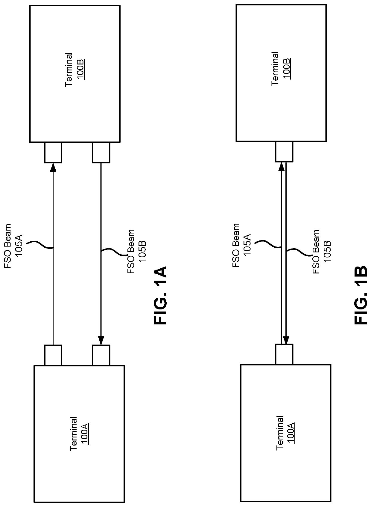
[0012]FIGS. 1A and 1B are block diagrams of terminals 100A and 100B communicating via free space optical (FSO) communications links, according to some embodiments. Specifically, the terminals 100 are communicating by transmitting and receiving data-encoded FSO beams 105. In FIG. 1A, each terminal 100 receives and transmits FSO beams 105 through different apertures, while in FIG. 1B, the terminals are co-boresighted so that beams are received and transmitted though the same aperture. As described herein, if terminal 100A is used as the frame of reference, terminal 100B may be referred to as a remote terminal, beam 105A may be r...


PUM


Abstract

Embodiments relate to a free space optical (FSO) communications system with a feed-forward control path. A data-encoded FSO beam is transmitted from a local terminal to a remote terminal. The local terminal directs a propagation direction of the FSO beam by a beam steering unit. To reduce pointing errors between the terminals, the FSO communications system includes a feed-forward control path. The control path includes an inertial measurement unit (IMU) that outputs motion data indicative of motion of the local terminal, for example if the local terminal is mounted to a tower that sways. The control path also includes a controller that receives the motion data from the IMU and generates feed-forward control signals for the beam steering unit. The control signals compensate for an effect of the motion of the local terminal on the propagation direction of the FSO beam.

Description

CROSS-REFERENCE TO RELATED APPLICATION[0001]This application claims priority under 35 U.S.C. § 119(e) to U.S. Provisional Patent Application Ser. No. 62 / 972,572, “Feed-Forward Control of Free Space Optical Communication System Based on Inertial Measurement Unit,” filed on Feb. 10, 2020, the content of which is incorporated herein by reference in its entirety.BACKGROUND1. Technical Field[0002]This disclosure relates generally to free space optical (FSO) communications and, more particularly, to reducing alignment errors due to movement of an FSO terminal.2. Description of Related Art[0003]Free space optical (FSO) communications is a communications technology that uses light propagating in free space to wirelessly transmit data, for example, for telecommunications or computer networking. Free space is a communications medium that can include water, air, outer space, or vacuum and contrasts with guided wave communications, such as optical fibers. FSO technology is useful where physical...

Claims


Application Information

Patent Timeline
Patent Type & Authority Patents(United States)
IPC IPC(8): H04B10/11H04B10/114H04L1/00
CPCH04B10/1143H04L1/0042H04B10/1123
Inventor DICKSON, WILLIAM C.
Owner PHOTONICS CORP
Why Eureka
Try Eureka