Multiple-Cavity Antenna

Active Publication Date: 2010-03-18
CARR WILLIAM N
View PDF39 Cites 13 Cited by
  • Summary
  • Abstract
  • Description
  • Claims
  • Application Information

AI Technical Summary

Benefits of technology

[0034]For situations where an RFID tag is used near a large metal object, embodiments of the present invention comprise an additional sheet of conductive material, referred to as a “reflector.” For embodiments implemented as a folded ribbon, the reflector sheet is placed parallel to the middle part of the ribbon

Problems solved by technology

The presence of the reflector reduces the disruption of tag perf

Method used


Image

  • Multiple-Cavity Antenna
  • Multiple-Cavity Antenna
  • Multiple-Cavity Antenna

Examples


Embodiment Construction

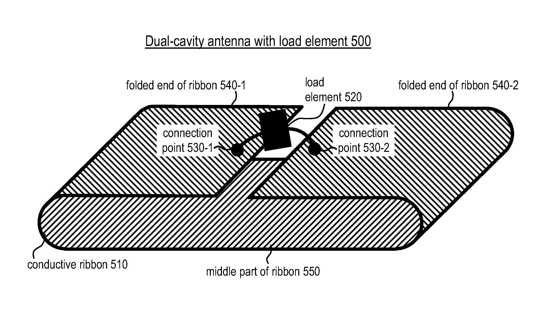
[0045]FIG. 5 depicts dual-cavity-antenna-with-load-element 500 in accordance with a first illustrative embodiment of the present invention. Dual-cavity-antenna-with-load-element 500 comprises: conductive ribbon 510, load element 520, and connection points 530-1 and 530-2 interrelated as shown. In particular, the two ends, 540-1 and 540-2, of conductive ribbon 510, are folded over the middle part 550 of conductive ribbon 510 and they are on the same side of the middle part 550 of conductive ribbon 510. The two folded ends 540-1 and 540-2 do not touch one another. Connection points 530-1 and 530-2 are on the two folded ends, 540-1 and 540-2, of conductive ribbon 510.

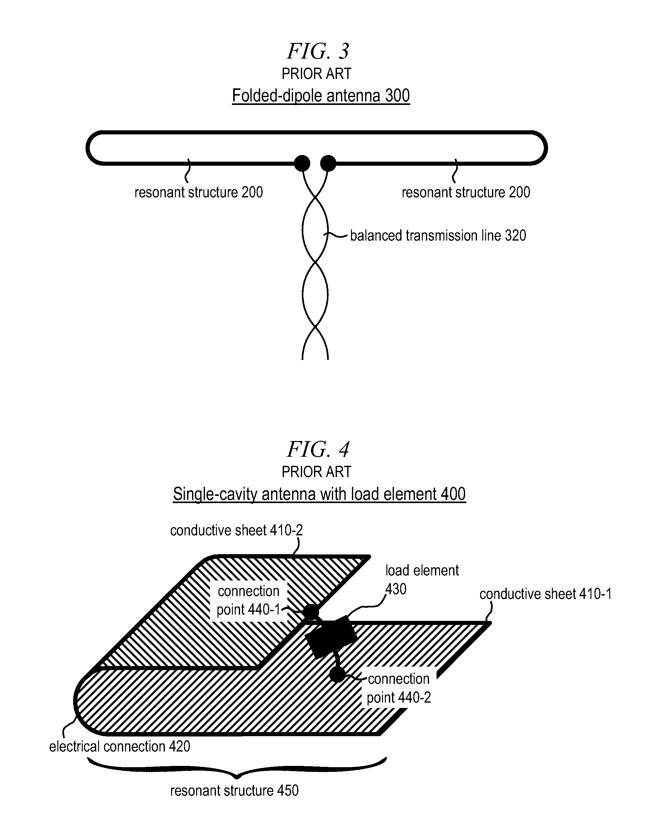
[0046]Each of the two folded ends 540-1 and 540-2 forms a resonant cavity together with the middle part 550 of conductive ribbon 510. The two cavities are electrically connected together via the shared middle part 550 of conductive ribbon 510. Compared to prior-art folded-dipole antenna 300, dual-cavity antenna with load e...


PUM


Abstract

An antenna for a Radio-Frequency IDentification (RFID) system is disclosed that comprises a pair of resonant cavities. The antenna is realized by folding the ends of a ribbon of conductive material, such as metal foil, over the middle part of the ribbon. The antenna generates a higher voltage than prior-art antennas used in RFID systems, and it makes possible RFID systems with an improved range. In an alternative embodiment, the antenna comprises a reflector that enables the RFID system to better tolerate the presence of nearby metal objects.

Description

CROSS REFERENCE TO RELATED APPLICATIONS[0001]The underlying concepts, but not necessarily the language, of the following cases are incorporated by reference:[0002](1) U.S. provisional application No. 61 / 207,467; and[0003](2) U.S. provisional application No. 61 / 273,814.If there are any contradictions or inconsistencies in language between this application and one or more of the cases that have been incorporated by reference that might affect the interpretation of the claims in this case, the claims in this case should be interpreted to be consistent with the language in this case.[0004]This case claims benefit of the following provisional applications:[0005](1) U.S. provisional application No. 61 / 207,467; and[0006](2) U.S. provisional application No. 61 / 273,814.[0007]This case is a Continuation-in-Part and claims priority of co-pending U.S. case No. 12 / 535,768 titled “Multiple-Resonator Antenna” and filed on Aug. 5, 2009.FIELD OF THE INVENTION[0008]The present invention relates to an...

Claims


Application Information

Patent Timeline
IPC IPC(8): H01Q1/36H01Q1/38H01Q23/00
CPCH01Q1/38H01Q1/2225H01Q23/00H01Q7/00H01Q13/08
Inventor CARR, WILLIAM N.
Owner CARR WILLIAM N
Why Eureka
Try Eureka