Device for Contact-Free Transmission of Signals and Measured Data in a Computed Tomography Apparatus

a computed tomography and signal technology, applied in tomography, instruments, applications, etc., can solve the problems of inability to transmit signals between a first transmission/reception device and a second transmission/reception device, low electromagnetic interference radiation radiation, etc., to achieve high data rate, reduce the rate of transmission, and build more simply and compact

Inactive Publication Date: 2007-10-18
SIEMENS HEALTHCARE GMBH
View PDF5 Cites 20 Cited by
  • Summary
  • Abstract
  • Description
  • Claims
  • Application Information

AI Technical Summary

Benefits of technology

[0032] According to a further embodiment of the invention, an encryption unit encrypts the data packets, advantageously according to 8B10B encryption. In 8B10B encryption an approximately constant signal intensity or light intensity is transmitted. The transmitted signals can thus be used for alignment of the transmission / reception devices. For example, without encryption a series of zero values of the intensity would be interpreted as a missing signal or incorrect alignment. Furthermore, the alignment units require no separate transmission / reception means. The transmission / reception devices can be built more simply and compact.
[0033] The 8B10B encryption of the data packets causes an increase of the number of the bits / s to be sent but the data rate of the transmission can be further reduced using compression methods.
[0034] According to a further embodiment of the invention, the transmission of the signals ensues with a data rate in the range of 1 to 100 gigabits per second (Gbps). Computed tomography systems with multi-line detectors, complicated acquisition protocols and control instructions require a reliable transmission with a high data rate. The inventive device enables a largely disruption-free transmission with data rates of 100 Gbps and more. The signals can be transmitted quickly and reliably even given short pulses and large data sets.
[0035] Furthermore, the alignment unit of the transmission / reception unit can include a detection unit for directed optical light signals or electromagnetic radio or hertzian waves. Optical light signals or electromagnetic waves can be used to monitor the alignment. It is in particular possible for the alignment unit to use the signals of the transmission / reception unit. No separate means for transmission of signals for alignment are necessary. In particular a mutual disruption of the signals of the alignment of the transmission / reception devices and the signals of the transmission of, for example, measurement data is avoided. The transmission / reception devices can be built simply, compact and cost-effectively.
[0036] Quadruple-photodetectors are particularly well suited for detection of direction changes of an optical light signal. These enable a precise and fast alignment and are particularly suitable for transmission / reception devices of a scanner rotating oppositely relative to one another.

Problems solved by technology

Furthermore, the radiation of electromagnetic interference radiation is low given the transmission with directed rays.
As a result of this a signal transmission between a first transmission / reception device and a second transmission / reception device is not possible at every angle position of the rotatable x-ray device.

Method used


Image

  • Device for Contact-Free Transmission of Signals and Measured Data in a Computed Tomography Apparatus
  • Device for Contact-Free Transmission of Signals and Measured Data in a Computed Tomography Apparatus
  • Device for Contact-Free Transmission of Signals and Measured Data in a Computed Tomography Apparatus

Examples


Embodiment Construction

[0043] For simplification, unidirectional transmission of signals is described. Transmission in the opposite direction ensues analogously. In particular a bidirectional transmission of signals is possible with the described device.

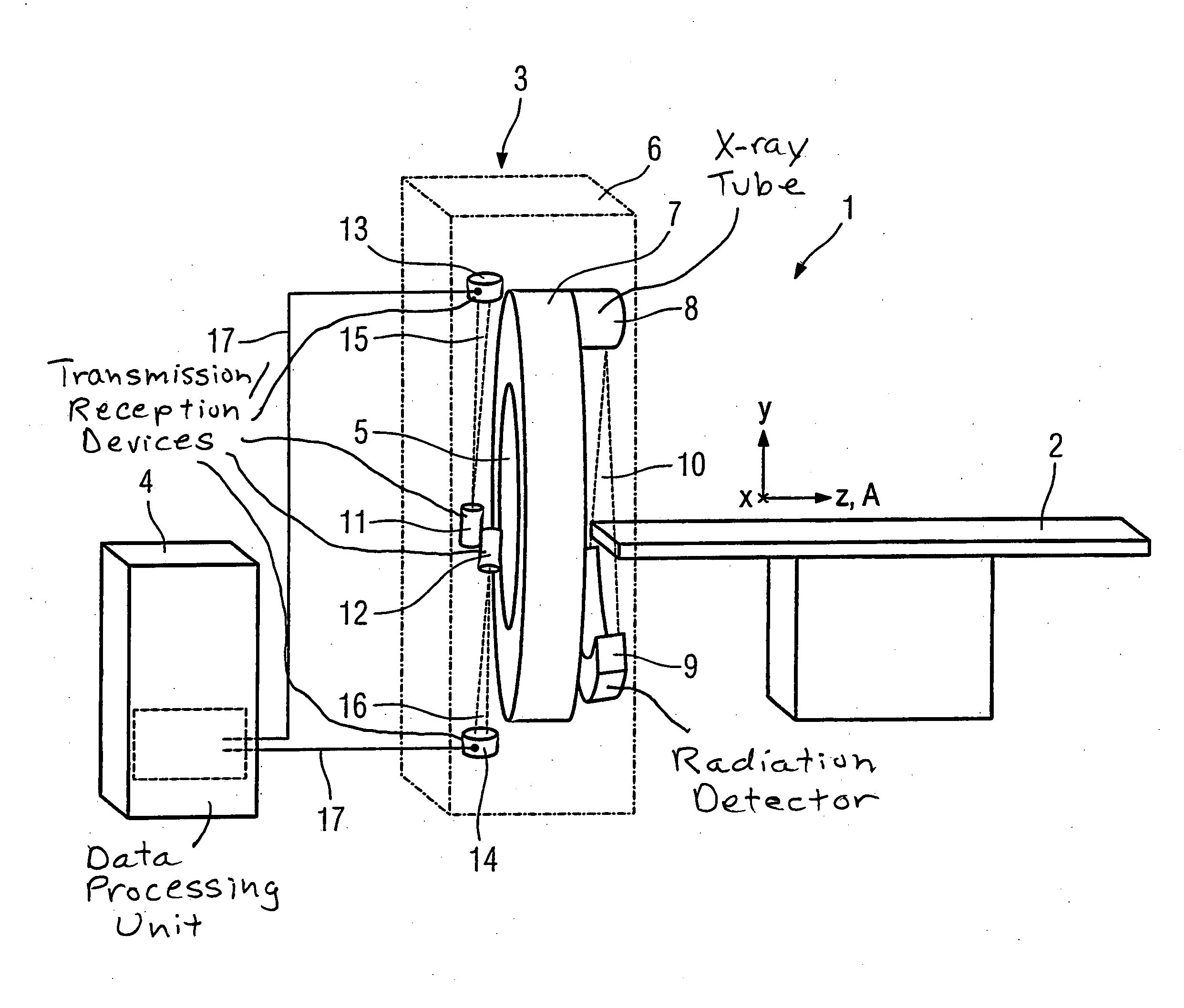
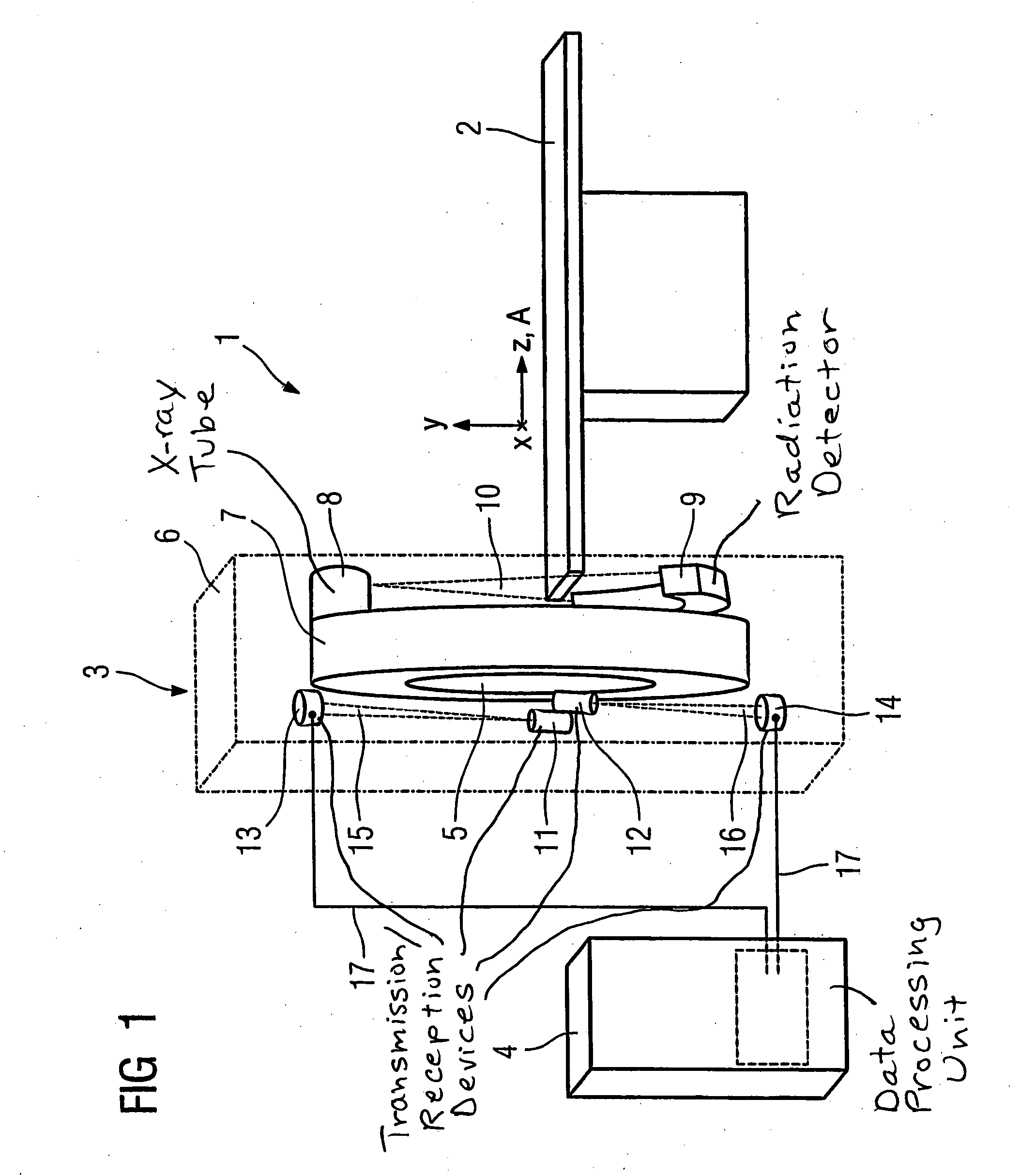
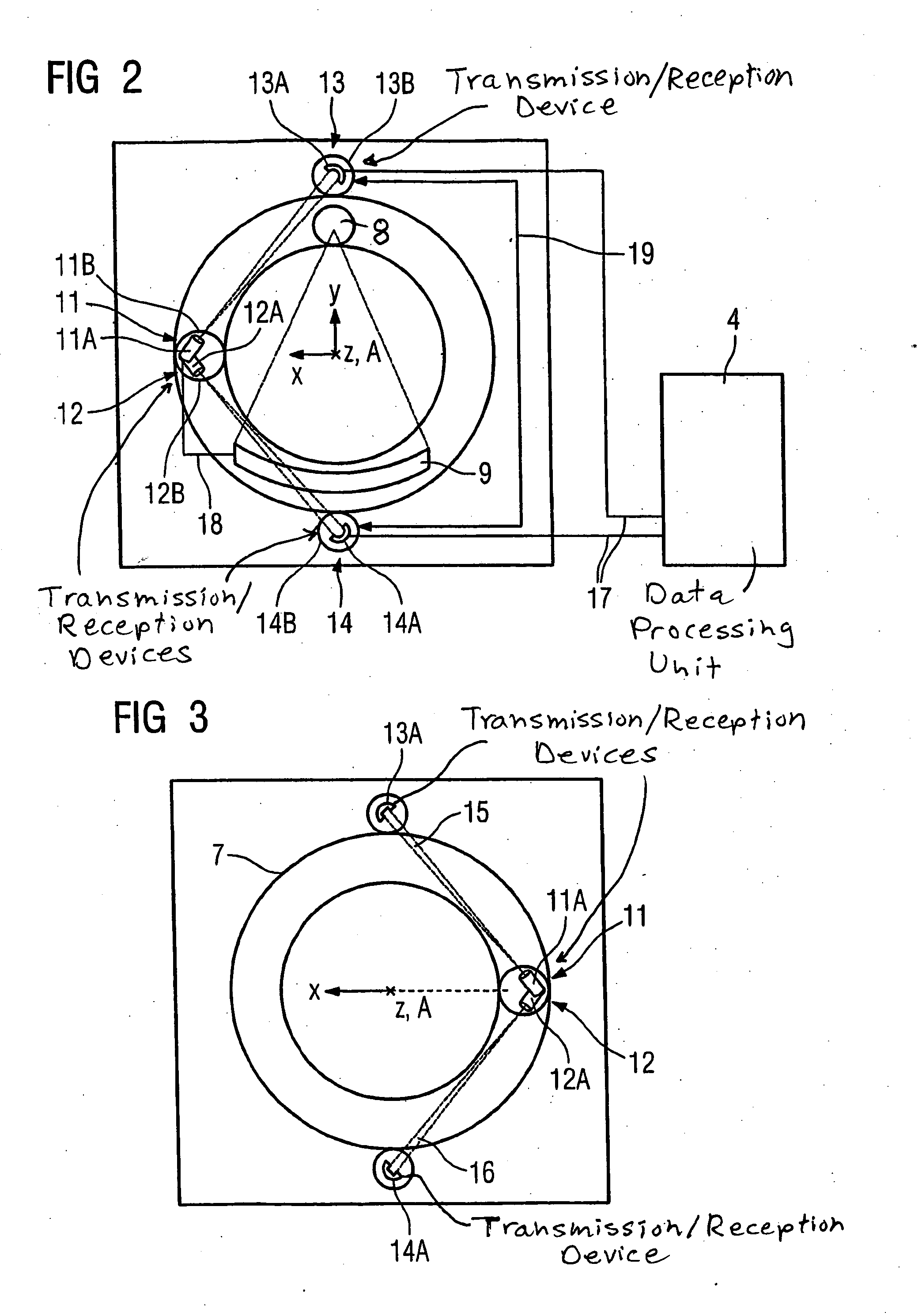
[0044]FIG. 1 shows a schematic design of a computed tomography scanner 1 with a patient bed 2, a gantry 3 and a data processing unit 4. The gantry 3 exhibits a central opening 5 into which the patient bed 2 with a patient located thereupon can be run in a z-direction given an examination. The gantry 3 has a stationary unit 6 and an x-ray device 7 rotatable around a z-axis A. The x-ray device 7 comprises an x-ray tube 8 and an oppositely-arranged detector 9. An x-ray beam emanating from the x-ray tube 8 is designated with the reference character 10. A second transmission / reception device 11 and a further second transmission / reception device 12 are mounted on the x-ray device 7. These are offset in the z-direction and mounted with the same radial separation...


PUM


Abstract

An x-ray computed tomography apparatus has a stationary unit and a rotatable unit, carrying an x-ray source and a radiation detector. The rotatable unit rotates around an axis relative to the stationary unit, that proceeds through both units. In order to transmit signals and measured data between the rotating unit and the stationary unit, transmitting/reception devices are mounted at each unit. The transmitting/reception devices transmit directed signals and are automatically oriented toward each other during relative movement caused by rotation of the rotating unit with respect to the stationary unit.

Description

BACKGROUND OF THE INVENTION [0001] 1. Field of the Invention [0002] The invention concerns a device for contact-less transmission of signals and measurement data between a rotatable part and a stationary part in a computed tomography apparatus. [0003] 2. Description of the Prior Art [0004] A device of the above type is known, for example, from U.S. Pat. No. 5,577,026. In this known device the signal is transmitted via antennas by means of electromagnetic radiation. [0005] A shortening of the antennas is required to increase the data rate of the transmission. The shorter the antennas, the more susceptible the transmission of the signals to external influences such as, for example, interferences or electromagnetic interference fields. A shortening of the antennas causes quality losses in the transmitted signal. [0006] For the transmission of signals via antennas as transmission / reception devices, a certain quantity of electromagnetic radiation is radiated into the environment. Electri...

Claims


Application Information

Patent Timeline
Patent Type & Authority Applications(United States)
IPC IPC(8): A61B6/00A61B5/00A61B6/03H01Q3/02H04B10/10H04B10/22
CPCA61B5/0017A61B5/7232A61B6/56A61B6/032
Inventor POPESCU, STEFAN
Owner SIEMENS HEALTHCARE GMBH
Why Eureka
Try Eureka