Mechanical circulatory support device with centrifugal impeller designed for implantation in the descending aorta

Active Publication Date: 2017-11-30
QUEEN MARY UNIV OF LONDON
View PDF2 Cites 19 Cited by
  • Summary
  • Abstract
  • Description
  • Claims
  • Application Information

AI Technical Summary

Benefits of technology

[0012]It is an object of the invention to provide a device that can be installed with less risk to the pati

Problems solved by technology

This in turn leads to poor organ perfusion and the symptoms of heart failure including fatigue, breathlessness and feeling generally unwell.
Poor kidney function means that patients feel more unwell, and important drugs have to be withdrawn as they can further adversely affect kidney function.
CHF is common and is a significant health care burden.
This percentage is higher than the actual number because most potential recipients are not included in the calculation; they are considered not suitable for a transplant because of co-morbidities or lack of a matched donor.
MCS devices are expensive and require invasive cardiac surgery (sternotomy or thoracotomy).
Implantation carries a significant risk.
Not all candidates are suitable for MCS because of co-morbidities.
Such “in-parallel” configurations involve the device and heart sharing, and therefore competing, for inlet

Method used


Image

  • Mechanical circulatory support device with centrifugal impeller designed for implantation in the descending aorta
  • Mechanical circulatory support device with centrifugal impeller designed for implantation in the descending aorta
  • Mechanical circulatory support device with centrifugal impeller designed for implantation in the descending aorta

Examples


Embodiment Construction

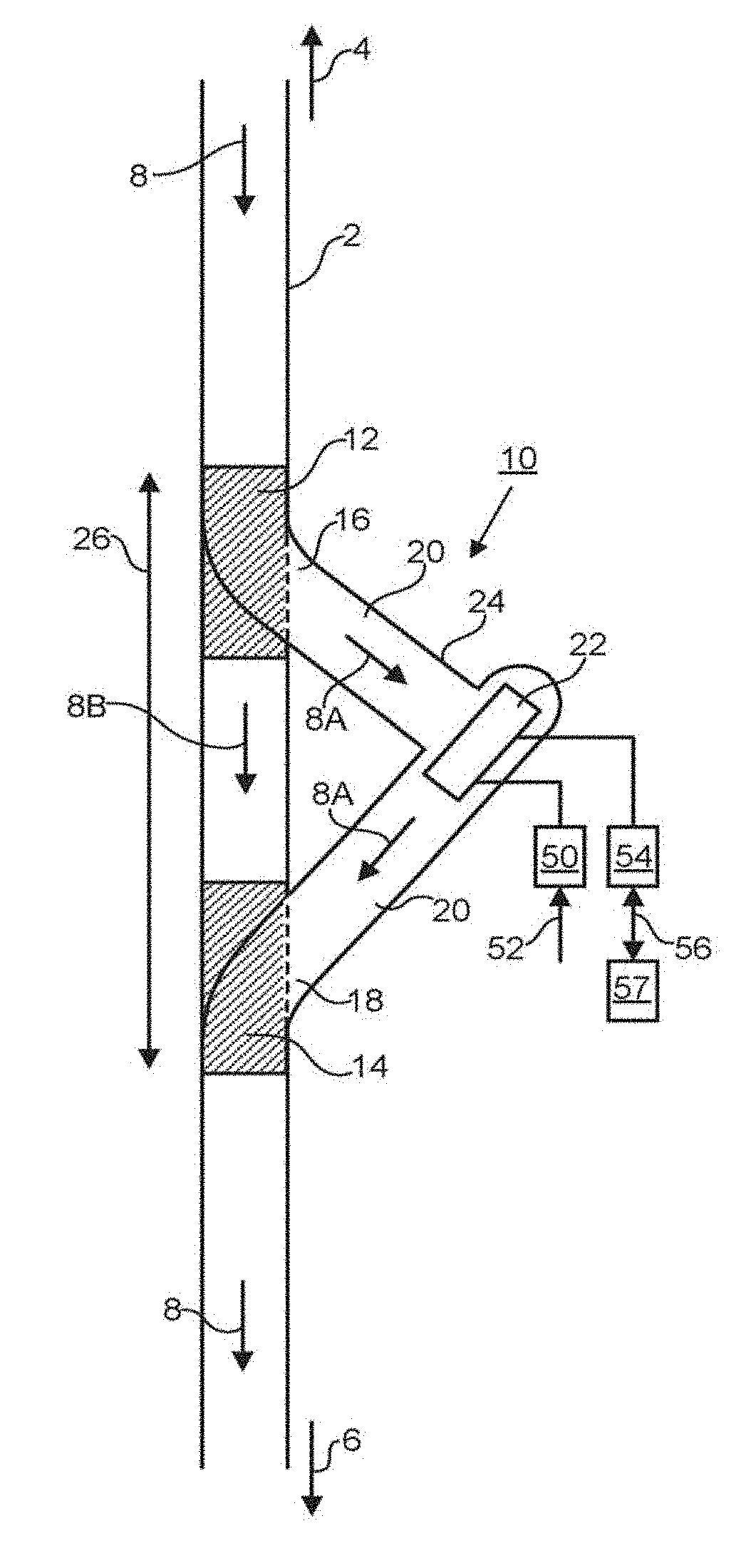
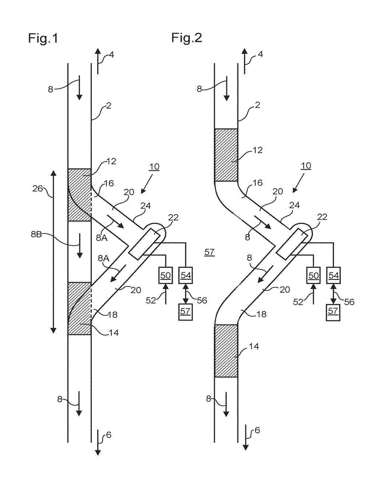
[0050]FIG. 1 depicts a section of vasculature 2. In an embodiment, the section of vasculature 2 comprises a section of the descending aorta. In an embodiment, the section of the descending aorta is below the diaphragm (arrow 4). In an embodiment, the section of the descending aorta is upstream and / or above the renal arteries and / or splanchnic arteries (arrow 6). Blood flow is shown schematically by arrows 8, 8A and 8B.

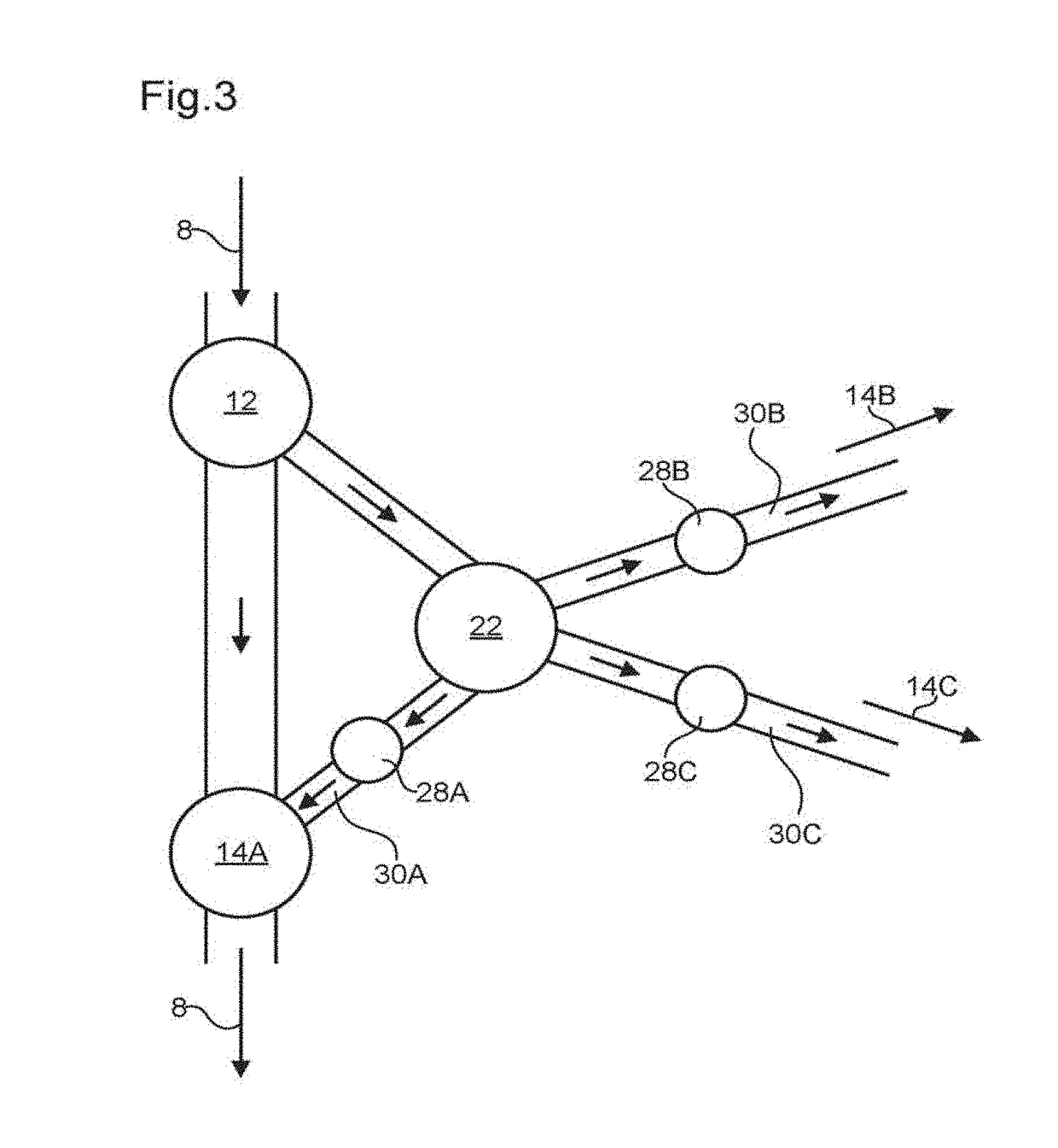
[0051]A mechanical circulatory support 10 comprises connections into (i.e. through the wall of) the vasculature via inlet port 12 and outlet port 14. The inlet port 12 is in fluid communication with a first end 16 of a lumen 20 defined by body portion 24 of the support 10. The outlet port 14 is in fluid communication with a second end 18 of the lumen 20. A pump 22 is provided within the lumen 20 and configured for driving fluid flow in a direction away from the inlet port 12 and towards the outlet port 14.

[0052]In an embodiment, the pump 22 is a centrifugal pump. The g...


PUM


Abstract

Mechanical circulatory supports configured to operate in series with the native heart are disclosed. In an embodiment, a centrifugal pump is used. In an embodiment, inlet and outlet ports are connected into the aorta and blood flow is diverted through a lumen and a centrifugal pump between the inlet and outlet ports. The supports may create a pressure rise between about 40-80 mmHg, and maintain a flow rate of about 5 L/min. The support may be configured to be inserted in a collinear manner with the descending aorta. The support may be optimized to replicate naturally occurring vortex formation within the aorta. Diffusers of different dimensions and configurations, such as helical configuration, and/or the orientation of installation may be used to optimize vortex formation. The support may use an impeller which is electromagnetically suspended, stabilized, and rotated to pump blood.

Description

INCORPORATION BY REFERENCE[0001]This application is a continuation-in-part of U.S. patent application Ser. No. 14 / 440,848, which is a U.S. national phase of PCT / GB2013 / 052889, filed Nov. 5, 2013, which claims priority to GB application No. 1219958.4, filed Nov. 6, 2012, which references are incorporated herein by reference in its entirety for all purposes. This application also claims priority benefit of U.S. Provisional Patent Application No. 62 / 403,428, filed Oct. 3, 2016, and U.S. Provisional Patent Application No. 62 / 513,927, filed Jun. 1, 2017, each of which is incorporated herein by reference in its entirety for all purposes. Any and all applications related thereto by way of priority thereto or therefrom are hereby incorporated by reference in their entirety.BACKGROUND[0002]The present invention relates to a mechanical circulatory support (MCS), otherwise known as a mechanical circulatory support device (MCSD), for assisting or replacing native heart function in cases of cong...

Claims


Application Information

Patent Timeline
IPC IPC(8): A61M1/10A61M1/12A61F2/06A61M60/139A61M60/221A61M60/232A61M60/237A61M60/30A61M60/422A61M60/531A61M60/546A61M60/562A61M60/876
CPCA61M1/1046A61M1/122A61F2/06A61M1/107A61M1/1008A61M60/562A61M60/422A61M60/896A61M60/232A61M60/531A61M60/30A61M60/221A61M60/546A61M60/139A61M60/237A61M60/876A61M60/148A61M60/274
Inventor KORAKIANITIS, THEODOSIOSROTHMAN, MARTIN T.
Owner QUEEN MARY UNIV OF LONDON
Why Eureka
Try Eureka