AI technical title is built by Patsnap AI team. It summarizes the technical point description of the patent document.
a material processing and surface processing technology, applied in metal-working apparatuses, welding apparatuses, manufacturing tools, etc., to achieve the effect of reducing disruption to activities within the structur
Inactive Publication Date: 2006-12-14
LOMA LINDA UNIV MEDICAL CENT
View PDF64 Cites 14 Cited by
Summary
Abstract
Description
Claims
Application Information
AI Technical Summary
This helps you quickly interpret patents by identifying the three key elements:
Problems solved by technology
Method used
Benefits of technology
Benefits of technology
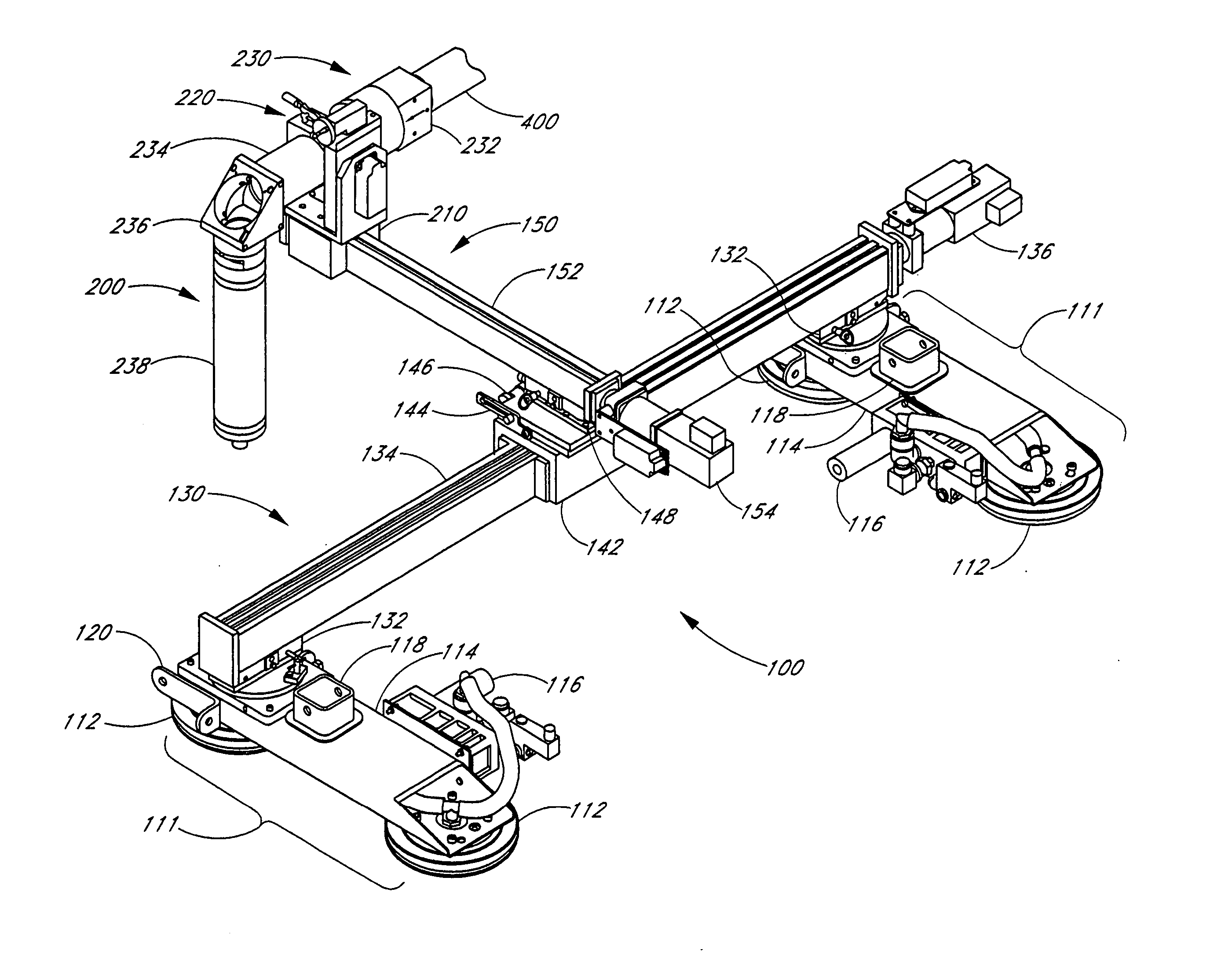
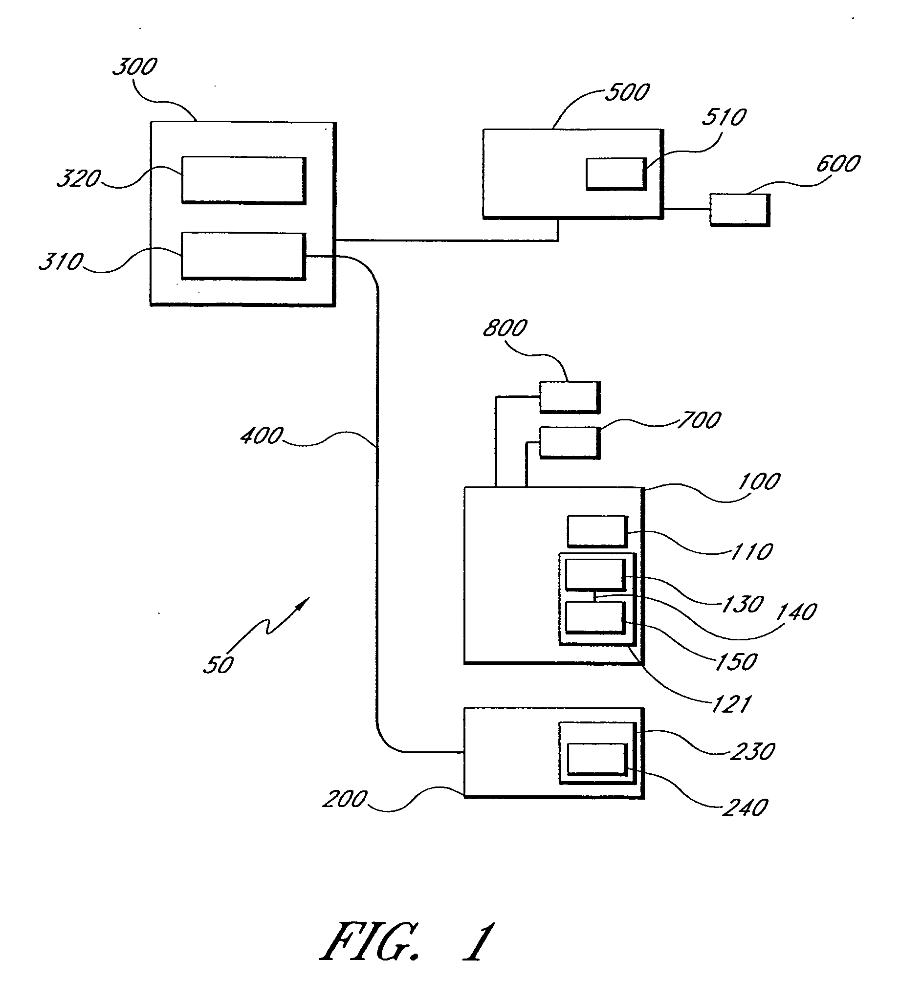
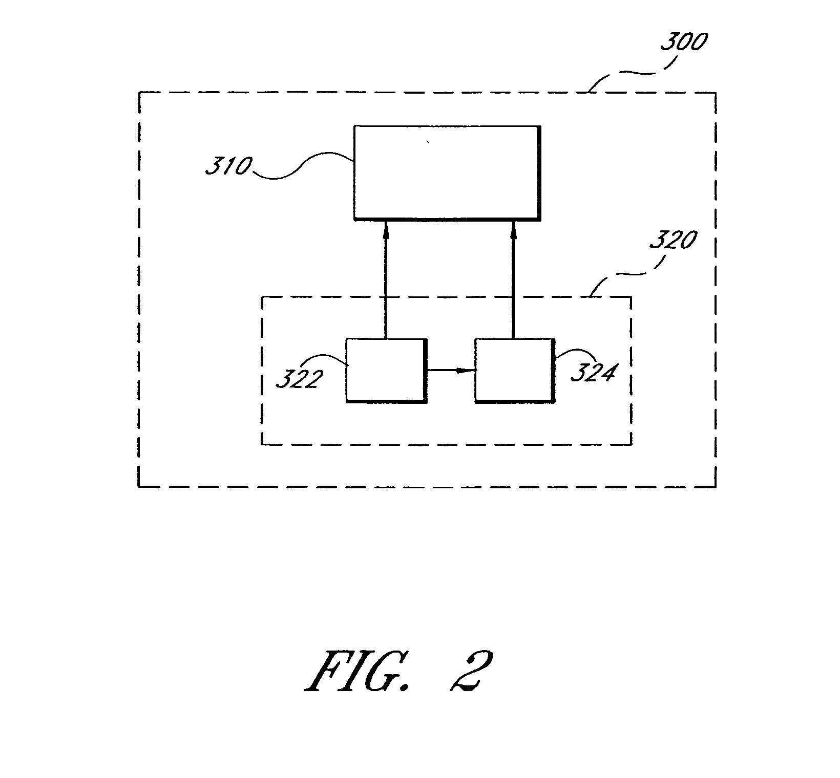
[0007] In certain embodiments, an apparatus processes a surface of an inhabitable structure. The apparatus comprises a laser base unit adapted to provide laser light to an interaction region, the laser light removing material from the structure. The laser base unit comprising a laser generator and a laser head coupled to the laser generator. The laser head is adapted to remove the material from the interaction region, thereby providing reduced disruption to activities within the structure. The apparatus further comprises a laser manipulation system. The laser manipulation system comprises an anchoring mechanism adapted to be releasably coupled to the structure. The laser manipulation system further comprises a positioning mechanism coupled to the anchoring mechanism and coupled to the laser head. The laser manipulation system is adapted to controllably adjust the position of the laser head relative to the structure. The apparatus further comprises a controller electrically coupled to the laser base unit and the laser manipulation system. The controller is adapted to transmit control signals to the laser base unit and to the laser manipulation system in response to user input.
[0008] In certain embodiments, an apparatus processes a surface of an inhabitable structure with reduced disruption to activities within the structure. The apparatus comprises means for generating laser light. The apparatus further comprises means for providing the laser light to an interaction region of the structure to remove material from the structure. The apparatus further comprises means for confining the material and removing the material from the interaction region. The apparatus further comprises means for controllably adjusting a position of the interaction region relative to the surface of the structure. The apparatus further comprises means for controlling the laser light and the position of the interaction region in response to user input.
[0009] In certain embodiments, a method processes a surface of an inhabitable structure with reduced disruption to activities within the structure. The method comprises remotely generating laser light. The method further comprises providing the laser light to the surface, the laser light interacting with the structure in an interaction region to remove material from the structure. The method further comprises confining the material and removing the material from the interaction region. The method further comprises controllably adjusting a position of the interaction region relative to the surface of the structure. The method further comprises controlling the laser light and the position of the interaction region in response to user input.
[0010] In certain embodiments, an apparatus processes a surface of an inhabitable structure. The apparatus comprises a base unit adapted to provide energy waves to an interaction region, the energy waves removing material from the structure. The base unit comprises a generator and a head coupled to the generator. The head is adapted to remove the material from the interaction region, thereby providing reduced disruption to activities within the structure. The apparatus further comprises a manipulation system. The manipulation system comprises an anchoring mechanism adapted to be releasably coupled to the structure. The manipulation system further comprises a positioning mechanism coupled to the anchoring mechanism and coupled to the head. The manipulation system is adapted to controllably adjust the position of the head relative to the structure. The apparatus further comprises a controller electrically coupled to the base unit and the manipulation system. The controller is adapted to transmit control signals to the base unit and to the manipulation system in response to user input.
Problems solved by technology
In the past, virtually all material processing, including drilling, cutting, scabbling, and the like have included numerous disruptive aspects (e.g., noise, vibration, dust, vapors, and fumes).
The '026 device requires mechanical drilling of materials such as concrete or other masonry, and generates all the disruptive aspects noted above.
Method used
Image
Click on the blue label to locate the original text in one second.
Reading with bidirectional positioning of images and text.
Examples
Embodiment Construction
[0041] Reducing the disruptive aspects of material processing has long been a goal of those in materials processing industries, particularly in industries that require materials processing within or near occupied structures, such as is common in renovation and many other applications. Such long-felt needs have been particularly prevalent in seismically active areas of the earth, where there is a pressing need for an effective and economical means of retrofitting occupied structures to increase the safety of these structures.
[0042] Prior technologies are plagued by disruptive characteristics, thereby making them virtually unsuitable for retrofitting occupied structures. Additionally, such material processing technologies often present dangerous and costly “cut through” dangers. “Cut through” dangers include instances such as a worker unintentionally cutting an embedded object while drilling through the subject material. For example, a construction worker drilling a hole in an existi...
PUM
Property
Measurement
Unit
cooling capacity
aaaaa
aaaaa
angle
aaaaa
aaaaa
angle
aaaaa
aaaaa
Abstract
An apparatus processes a surface of an inhabitable structure. The apparatus includes a base unit adapted to provide energy waves to an interaction region, the energy waves removing material from the structure. The base unit includes an energy wave generator and a head coupled to the energy wave generator. The head is adapted to remove the material from the interaction region, thereby providing reduced disruption to activities within the structure. The apparatus further includes a manipulation system which includes an anchoring mechanism adapted to be releasably coupled to the structure and a positioning mechanism coupled to the anchoring mechanism and coupled to the head. The manipulation system is adapted to controllably adjust the position of the head relative to the structure. The apparatus further includes a controller electrically coupled to the base unit. The controller is adapted to transmit control signals to the base unit in response to user input.
Description
RELATED APPLICATIONS [0001] This application is a continuation of U.S. patent application Ser. No. 10 / 690,983, filed Oct. 22, 2003, which is incorporated in its entirety by reference herein, and which claims benefit under 35 U.S.C. §119(e) to U.S. Provisional Patent Application No. 60 / 456,043, filed Mar. 18, 2003, to U.S. Provisional Patent Application No. 60 / 471,057, filed May 16, 2003, and to U.S. Provisional Patent Application No. 60 / 496,460, filed Aug. 20, 2003, each of which is incorporated in its entirety by reference herein. This application is related to U.S. patent application Ser. Nos. 10 / 690,833, 10 / 690,975, 10 / 691,481, and 10 / 691,444, each of which was filed on Oct. 22, 2003 and is incorporated in its entirety by reference herein. This application is also related to U.S. patent application Ser. Nos. 10 / 803,272, 10 / 803,243, and 10 / 803,267, each of which was filed on Mar. 18, 2004 and is incorporated in its entirety by reference herein. This application is also related to ...
Claims
Application Information
Patent Timeline
Application Date:The date an application was filed.
Publication Date:The date a patent or application was officially published.
First Publication Date:The earliest publication date of a patent with the same application number.
Issue Date:Publication date of the patent grant document.
PCT Entry Date:The Entry date of PCT National Phase.
Estimated Expiry Date:The statutory expiry date of a patent right according to the Patent Law, and it is the longest term of protection that the patent right can achieve without the termination of the patent right due to other reasons(Term extension factor has been taken into account ).
Invalid Date:Actual expiry date is based on effective date or publication date of legal transaction data of invalid patent.
Patent Type & AuthorityApplications(United States)

